Reddit mentions: The best electrical motor controls
We found 151 Reddit comments discussing the best electrical motor controls. We ran sentiment analysis on each of these comments to determine how redditors feel about different products. We found 77 products and ranked them based on the amount of positive reactions they received. Here are the top 20.
1. Qunqi L298N Motor Drive Controller Board Module Dual H Bridge DC Stepper For Arduino
- Dual-channel H-bridge driver working mode creates higher working efficiency,L298N as main chip.Can drive one 2-phase stepper motor, one 4-phase stepper motor or two DC motors.
- To avoid damage the voltage stabilizing chip, please use an external 5V logic supply when using more than 12V driving voltage
- Use large-capacity filter capacitors and diode with freewheeling protection function, increasing reliability
- High working power to 35v,large current can reach 3A MAX and continue current is 2A, power to 25w.
- Large capacity filter capacitance,afterflow protection diode, more stable and reliable.
Features:

Specs:
| Height | 0.7480314953 Inches |
| Length | 1.1417322823 Inches |
| Weight | 0.07 Pounds |
| Width | 0.9842519675 Inches |
2. L298N H-bridge Motor Controller, DROK L298N Motor Driver Board DC Dual H Bridge Robot Stepper Motor Regulator and Drives Module for Arduino Smart Car Power UNO MEGA R3 Mega2560 Duemilanove
DROK L298N h-bridge motor controller working mode creates higher working efficiency, L298N as main chip, ST corporation production. Can drive one 2-phase stepper motor, one 4-phase stepper motor or two DC motors.To avoid damage the voltage stabilizing chip, please use an external 5V logic supply whe...
Specs:
| Height | 5.5 Inches |
| Length | 7 Inches |
| Weight | 0.06625 Pounds |
| Width | 1.5 Inches |
| Size | L289N |
| Number of items | 1 |
3. RioRand RR-PWM-15V Low Voltage Dc 1.8v 3v 5v 6v 12v 2a Motor Speed Controller Pwm,
Low Voltage DC 1.8V 3V 5V 6V 12V 2AMotor Speed Controller PWMThe maximum output power: 30WDuty Cycle adjustable: 0%-100%

Specs:
| Color | 2A PWM |
| Height | 0.7 Inches |
| Length | 3.5 Inches |
| Weight | 0.02 Kilograms |
| Width | 2.1 Inches |
| Number of items | 1 |
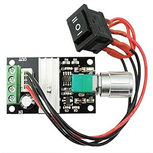
4. RioRand 7-70V PWM DC Motor Speed Controller Switch 30A
Potentiometer cable(about 15CM) can be separated, with running stop brake functionSuitable for long hours of work:Circuit optimization design,stableAdjust the motor smooth no noise no vibration,with power indication,wide duty cycle adjustment rangeUsing imported high-voltage MOS tube, three pres...
Specs:
| Color | Green |
| Height | 1.4 Inches |
| Length | 3.4 Inches |
| Width | 2.3 Inches |
| Number of items | 1 |
5. STEPPERONLINE CNC Stepper Motor Driver 1.0-4.2A 20-50VDC 1/128 Micro-Step Resolutions for Nema 17 and 23 Stepper Motor
- Stepper motor driver DM542T is updated to version V4.0, add 5V/24V logical voltage selector, alarm outputs. Please attension, Factory setting is 24V, if you need to use 5V, switch selector on the top of the driver.
- Industrial-grade Stepper Driver, Suit for Nema 17 and 23 Stepper Motor
- 1.0~4.2A, 20~50VDC, 1/128 Microstep Resolution
- Pulse signal: 4-5V when PUL-HIGH, 0-0.5V whenPUL-LOW. The same as DIR and ENA signals
- 100% service satisfactory. We provided this stepper motor kit with 30 days free replacement or refund, 1 year warranty and whole life customer service from the date of purchasing.
Features:
Specs:
| Weight | 0.4629707502 Pounds |
6. uniquegoods 6V 12V 24V Digital Display LED DC Motor Speed Controller PWM Stepless Speed Control Switch HHO Driver - Black CCM5D
- Input supply voltage: 6V-30V DC
- PWM frequency: 16kHz; Duty Cycle adjustable: 0%-100%
- Item size: 3.1*1.6*0.9 inches ; Net weight: 2.1 ounces
- The maximum output power: 240W
- The maximum continuous output current :5A;(Peak current 8A),The LED display the duty ratio 0-100%
Features:

Specs:
| Height | 1.6 Inches |
| Length | 3.1 Inches |
| Weight | 0.13125 Pounds |
| Width | 0.9 Inches |
7. KB Electronics 8811006 Solid State Variable Speed AC Electric Motor Control, 2.5 Max amp, 115V, # K177-1002
- Designed for Standard 2" x 4" Electrical Wall Box
- 2.5 Max amps 115 Volts; UL & CSA Approved
- Not to be used with Capacitor Start or Capacitor Run Motors
- Applications: Fans, Blowers, Fireplace Blowers, Attic Fans, Humidifiers, Ventilators
Features:

Specs:
| Weight | 0.01 Pounds |
| Size | 2.5 Amp |
| Number of items | 1 |
8. High Torque Nema 23 CNC Stepper Motor 114mm 425oz.in/3Nm CNC Mill Lathe Router
Very Huge Torque3Nm(425oz.in) holding torqueNEMA 23 bipolar 2.24"x2.24"x4.45" 4-wire1.8 deg. step angle(200 steps/rev)Rated current 4.2A & resistance 0.9ohms

Specs:
| Height | 2.24409 Inches |
| Length | 2.24409 Inches |
| Weight | 3.69 pounds |
| Width | 4.44881 Inches |
9. KB Electronics 8811012 Solid State Variable Speed AC Electric Motor Control, 5.0 Max amp, 115V, # K177-1005
- Designed for Standard 2" x 4" Electrical Wall Box
- 5.0 Max amps 115 Volts; UL & CSA Approved
- Not to be used with Capacitor Start or Capacitor Run Motors
- Applications: Fans, Blowers, Fireplace Blowers, Attic Fans, Humidifiers, Ventilators
Features:
Specs:
| Weight | 0.31 Pounds |
| Size | 5.0 Amp |
| Number of items | 1 |
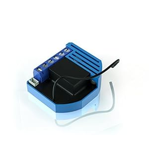
10. Qubino Z-Wave Plus Universal Relay with Dry Contact Switch ZMNHND3
WHAT DOES IT DO? Install it behind your push-button garage opener switch, or at the low-voltage installation for your fireplace, or any dry contact circuit to get on/off Z-Wave control and status updates to your smart home hub.WHAT ELSE DO I NEED? Check for NEUTRAL wire in the switch box (VERY IMPOR...
Specs:
| Height | 1.574803148 Inches |
| Length | 0.393700787 Inches |
| Width | 1.574803148 Inches |
11. uniquegoods AC 220V 80A 10000W High Power Digital SCR PWM Motor Speed Controller Voltage Regulator Dimming Control Attemperation Thermoregulation
Parameter: Use voltage: AC 220V. Maximum power: 10000W.Voltage regulation: 0-100% (220 volts, 100-level adjustment, non-linear).Features: Using the new two-way high-power SCR, max current up to 80A.The voltage regulator with the peak voltage absorption circuit effectively protects the high-power SCR...

Specs:
| Weight | 0.2 Pounds |
12. Nema 34 Stepper Motor 6A 12Nm (1700 oz-in) 156mm Length for CNC Router Mill Lathe
- Nema 34 156mm length stepper motor.
- Holding Torque: 12Nm (1700oz.in)
- Weight: 5.2kg
Features:

Specs:
| Color | Black |
| Weight | 11.464037624 Pounds |
13. uniquegoods 6V 12V 24V 28V 3A 80W DC Motor Speed Controller (PWM) Speed Adjustable Reversible Switch 1203BB DC Motor Driver Reversing
Package:1 x dc motor speed controllerItem size: 1.3*2*0.4 inches; Net Weight:1.13 ouncesDuty Cycle adjustable: 5%-100%, potentiometer with switch function.The maximum output power: 80WThe maximum continuous output current :3A
Specs:
| Height | 0.4 Inches |
| Length | 2 Inches |
| Weight | 0.07 Pounds |
| Width | 1.3 Inches |
14. QUBINO Flush ZMNHBD3 Z-Wave 2 relays - the smallest double relay switch
- Z-Wave Plus relay module adds individual and grouped On/Off commands to two devices
- Compatible with toggle and pushbutton switches, as well as plug-in outlets
- Add delayed/scheduled/responsive triggers to connected devices
- Small device size allows for quick and easy installation in nearly any setting
- Optional sensor input enables responsive automation scene implementation
Features:
 ▼ Read Reddit mentions
15. MagiDeal 5 Pieces 3D Printer Stepper Motor Driver Module TMC2130 Stepper Motor Driver
1.2A two-phase stepper motor single-phase current (peak 2.5A); adjustable motor operating current.Support two control methods: Step / DIR interface and SPI interface control.256 subdivision.Maximum efficiency and optimum motor torque operation without noise.Motor input voltage range: 4.75 ~ 46V Logi...
 ▼ Read Reddit mentions
16. Rf Remote , 12 V 315 MHZ 2 Channel wireless Control Switch Transmitter and Receiver with battery(2CH)
EASY to INSTALL,Wireless controlGOOD WIRELESS RF SIGNAL,it can pass through walls, floors and doors,control receiver from any place within a reliable distance.WIDE USE It applies to remote control motor reversing, bumper gate, electric doors and windows, electric dining table, showcase, a variety of...
 ▼ Read Reddit mentions
17. Qubino Z-Wave Plus Flush Dimmer ZMNHDD3 - First truly universal Z-Wave micro dimmer
- The adjustable waist range is 27.5in-39.3in, which is suitable for most women.Receive 1 * Leather Necklace (B07MZRHKCC) free when you purchase 1 * Leg Harness Style 5 offered by homelix. Enter code AQ6IJSSO at checkout.
- Three-layer composite PU , absolute thickness, super high-quality on the front, very soft; soft and non-irritating flannel on the bottom, no cold when in contact with the skin, no deformation under any pressure.
- Great for LARP (live action role playing), kids, cosplay, Halloween, fancy dress, theatrical props, and historical reenactments.
- Can be used with daily dress up, this will bring more highlights to your style of dress,If you need to wear special occasions such as clubs, concerts , it will make you look special and beautiful.
- Provides exactly what you need to complete that perfect look. Harness is Fully Wearable and Comfortably made.
Features:
▼ Read Reddit mentions18. Honeywell 802360JA Motor
- Voltage: 24V;
- Frequency: 50/60Hz;
- Electrical Connections: 6" Leads;
- Brand Name: Honeywell
Features:

Specs:
| Color | 2 |
| Height | 2 Inches |
| Length | 2 Inches |
| Weight | 0.26896395964 Pounds |
| Width | 2 Inches |
| Number of items | 1 |
19. Qubino Z-Wave Plus RGBW Controller ZMNHWD3 for 12-24V LED Strips and Light Bulbs
WHAT DOES IT DO? Connect it to your 12-24VDC RGBW LED strip for Z-Wave wireless control. Dim and control 16 million shades.WHAT ELSE DO I NEED? A matching power supply for the Qubino, so if your strip runs on 12VDC, get a 12 VDC power supply, if it needs 24 VDC, power the Qubino with 24 VDC (VERY IM...

Specs:
| Height | 0.57 Inches |
| Length | 1.77 Inches |
| Weight | 0.06 Pounds |
| Width | 1.25 Inches |
20. Electric 12vdc Reversible 36 Rpm Dc Gear Motor for DIY Parts
- ✔Rated voltage: DC12V; No-load speed: 36RPM; Rated torque: 1.375kg.cm; Rated Current: 0.27A;
- ✔Reduction ratio: 1/255; Protection class: IP54; Low noise: db<45 (A); Certification: CE; Material: Metal; Commutation: Brush;
- ✔Gear Motor Body Dimensions: 3 x 1.25 x 1.06inches(L*W*H); Out Shaft Dimensions: 0.53*0.23inches(L*D) with 0.047*0.43inches flat cut off;
- ✔Usage: windows and doors, household electrical appliances, Car, Boat and Robot model, DIY engine, home automation, mini winch and other occasions;
- ✔Package: 1PCS x DC Geared Motor; if you need other voltage and rpm, pls contact us, there are many other models of this motor in store.
Features:
 ▼ Read Reddit mentions
🎓 Reddit experts on electrical motor controls
The comments and opinions expressed on this page are written exclusively by redditors. To provide you with the most relevant data, we sourced opinions from the most knowledgeable Reddit users based the total number of upvotes and downvotes received across comments on subreddits where electrical motor controls are discussed. For your reference and for the sake of transparency, here are the specialists whose opinions mattered the most in our ranking.
Interested in what Redditors like? Check out our Shuffle feature
Shuffle: random products popular on RedditTop Reddit comments about Electrical Motor Controls:
Summary
1. Qunqi L298N Motor Drive Controller Board Module Dual H Bridge DC Stepper For Arduino
- Dual-channel H-bridge driver working mode creates higher working efficiency,L298N as main chip.Can drive one 2-phase stepper motor, one 4-phase stepper motor or two DC motors.
- To avoid damage the voltage stabilizing chip, please use an external 5V logic supply when using more than 12V driving voltage
- Use large-capacity filter capacitors and diode with freewheeling protection function, increasing reliability
- High working power to 35v,large current can reach 3A MAX and continue current is 2A, power to 25w.
- Large capacity filter capacitance,afterflow protection diode, more stable and reliable.
Features:
Specs:
| Height | 0.7480314953 Inches |
| Length | 1.1417322823 Inches |
| Weight | 0.07 Pounds |
| Width | 0.9842519675 Inches |
2. L298N H-bridge Motor Controller, DROK L298N Motor Driver Board DC Dual H Bridge Robot Stepper Motor Regulator and Drives Module for Arduino Smart Car Power UNO MEGA R3 Mega2560 Duemilanove
DROK L298N h-bridge motor controller working mode creates higher working efficiency, L298N as main chip, ST corporation production. Can drive one 2-phase stepper motor, one 4-phase stepper motor or two DC motors.To avoid damage the voltage stabilizing chip, please use an external 5V logic supply whe...
Specs:
| Height | 5.5 Inches |
| Length | 7 Inches |
| Weight | 0.06625 Pounds |
| Width | 1.5 Inches |
| Size | L289N |
| Number of items | 1 |
3. RioRand RR-PWM-15V Low Voltage Dc 1.8v 3v 5v 6v 12v 2a Motor Speed Controller Pwm,
Low Voltage DC 1.8V 3V 5V 6V 12V 2AMotor Speed Controller PWMThe maximum output power: 30WDuty Cycle adjustable: 0%-100%
Specs:
| Color | 2A PWM |
| Height | 0.7 Inches |
| Length | 3.5 Inches |
| Weight | 0.02 Kilograms |
| Width | 2.1 Inches |
| Number of items | 1 |
4. RioRand 7-70V PWM DC Motor Speed Controller Switch 30A
Potentiometer cable(about 15CM) can be separated, with running stop brake functionSuitable for long hours of work:Circuit optimization design,stableAdjust the motor smooth no noise no vibration,with power indication,wide duty cycle adjustment rangeUsing imported high-voltage MOS tube, three pres...
Specs:
| Color | Green |
| Height | 1.4 Inches |
| Length | 3.4 Inches |
| Width | 2.3 Inches |
| Number of items | 1 |
5. STEPPERONLINE CNC Stepper Motor Driver 1.0-4.2A 20-50VDC 1/128 Micro-Step Resolutions for Nema 17 and 23 Stepper Motor
- Stepper motor driver DM542T is updated to version V4.0, add 5V/24V logical voltage selector, alarm outputs. Please attension, Factory setting is 24V, if you need to use 5V, switch selector on the top of the driver.
- Industrial-grade Stepper Driver, Suit for Nema 17 and 23 Stepper Motor
- 1.0~4.2A, 20~50VDC, 1/128 Microstep Resolution
- Pulse signal: 4-5V when PUL-HIGH, 0-0.5V whenPUL-LOW. The same as DIR and ENA signals
- 100% service satisfactory. We provided this stepper motor kit with 30 days free replacement or refund, 1 year warranty and whole life customer service from the date of purchasing.
Features:
Specs:
| Weight | 0.4629707502 Pounds |
6. uniquegoods 6V 12V 24V Digital Display LED DC Motor Speed Controller PWM Stepless Speed Control Switch HHO Driver - Black CCM5D
- Input supply voltage: 6V-30V DC
- PWM frequency: 16kHz; Duty Cycle adjustable: 0%-100%
- Item size: 3.1*1.6*0.9 inches ; Net weight: 2.1 ounces
- The maximum output power: 240W
- The maximum continuous output current :5A;(Peak current 8A),The LED display the duty ratio 0-100%
Features:
Specs:
| Height | 1.6 Inches |
| Length | 3.1 Inches |
| Weight | 0.13125 Pounds |
| Width | 0.9 Inches |
7. KB Electronics 8811006 Solid State Variable Speed AC Electric Motor Control, 2.5 Max amp, 115V, # K177-1002
- Designed for Standard 2" x 4" Electrical Wall Box
- 2.5 Max amps 115 Volts; UL & CSA Approved
- Not to be used with Capacitor Start or Capacitor Run Motors
- Applications: Fans, Blowers, Fireplace Blowers, Attic Fans, Humidifiers, Ventilators
Features:
Specs:
| Weight | 0.01 Pounds |
| Size | 2.5 Amp |
| Number of items | 1 |
8. High Torque Nema 23 CNC Stepper Motor 114mm 425oz.in/3Nm CNC Mill Lathe Router
Very Huge Torque3Nm(425oz.in) holding torqueNEMA 23 bipolar 2.24"x2.24"x4.45" 4-wire1.8 deg. step angle(200 steps/rev)Rated current 4.2A & resistance 0.9ohms
Specs:
| Height | 2.24409 Inches |
| Length | 2.24409 Inches |
| Weight | 3.69 pounds |
| Width | 4.44881 Inches |
9. KB Electronics 8811012 Solid State Variable Speed AC Electric Motor Control, 5.0 Max amp, 115V, # K177-1005
- Designed for Standard 2" x 4" Electrical Wall Box
- 5.0 Max amps 115 Volts; UL & CSA Approved
- Not to be used with Capacitor Start or Capacitor Run Motors
- Applications: Fans, Blowers, Fireplace Blowers, Attic Fans, Humidifiers, Ventilators
Features:
Specs:
| Weight | 0.31 Pounds |
| Size | 5.0 Amp |
| Number of items | 1 |
10. Qubino Z-Wave Plus Universal Relay with Dry Contact Switch ZMNHND3
WHAT DOES IT DO? Install it behind your push-button garage opener switch, or at the low-voltage installation for your fireplace, or any dry contact circuit to get on/off Z-Wave control and status updates to your smart home hub.WHAT ELSE DO I NEED? Check for NEUTRAL wire in the switch box (VERY IMPOR...
Specs:
| Height | 1.574803148 Inches |
| Length | 0.393700787 Inches |
| Width | 1.574803148 Inches |
11. uniquegoods AC 220V 80A 10000W High Power Digital SCR PWM Motor Speed Controller Voltage Regulator Dimming Control Attemperation Thermoregulation
Parameter: Use voltage: AC 220V. Maximum power: 10000W.Voltage regulation: 0-100% (220 volts, 100-level adjustment, non-linear).Features: Using the new two-way high-power SCR, max current up to 80A.The voltage regulator with the peak voltage absorption circuit effectively protects the high-power SCR...
Specs:
| Weight | 0.2 Pounds |
12. Nema 34 Stepper Motor 6A 12Nm (1700 oz-in) 156mm Length for CNC Router Mill Lathe
- Nema 34 156mm length stepper motor.
- Holding Torque: 12Nm (1700oz.in)
- Weight: 5.2kg
Features:
Specs:
| Color | Black |
| Weight | 11.464037624 Pounds |
13. uniquegoods 6V 12V 24V 28V 3A 80W DC Motor Speed Controller (PWM) Speed Adjustable Reversible Switch 1203BB DC Motor Driver Reversing
Package:1 x dc motor speed controllerItem size: 1.3*2*0.4 inches; Net Weight:1.13 ouncesDuty Cycle adjustable: 5%-100%, potentiometer with switch function.The maximum output power: 80WThe maximum continuous output current :3A
Specs:
| Height | 0.4 Inches |
| Length | 2 Inches |
| Weight | 0.07 Pounds |
| Width | 1.3 Inches |
14. QUBINO Flush ZMNHBD3 Z-Wave 2 relays - the smallest double relay switch
- Z-Wave Plus relay module adds individual and grouped On/Off commands to two devices
- Compatible with toggle and pushbutton switches, as well as plug-in outlets
- Add delayed/scheduled/responsive triggers to connected devices
- Small device size allows for quick and easy installation in nearly any setting
- Optional sensor input enables responsive automation scene implementation
Features:
▼ Read Reddit mentions15. MagiDeal 5 Pieces 3D Printer Stepper Motor Driver Module TMC2130 Stepper Motor Driver
1.2A two-phase stepper motor single-phase current (peak 2.5A); adjustable motor operating current.Support two control methods: Step / DIR interface and SPI interface control.256 subdivision.Maximum efficiency and optimum motor torque operation without noise.Motor input voltage range: 4.75 ~ 46V Logi...
▼ Read Reddit mentions16. Rf Remote , 12 V 315 MHZ 2 Channel wireless Control Switch Transmitter and Receiver with battery(2CH)
EASY to INSTALL,Wireless controlGOOD WIRELESS RF SIGNAL,it can pass through walls, floors and doors,control receiver from any place within a reliable distance.WIDE USE It applies to remote control motor reversing, bumper gate, electric doors and windows, electric dining table, showcase, a variety of...
▼ Read Reddit mentions17. Qubino Z-Wave Plus Flush Dimmer ZMNHDD3 - First truly universal Z-Wave micro dimmer
- The adjustable waist range is 27.5in-39.3in, which is suitable for most women.Receive 1 * Leather Necklace (B07MZRHKCC) free when you purchase 1 * Leg Harness Style 5 offered by homelix. Enter code AQ6IJSSO at checkout.
- Three-layer composite PU , absolute thickness, super high-quality on the front, very soft; soft and non-irritating flannel on the bottom, no cold when in contact with the skin, no deformation under any pressure.
- Great for LARP (live action role playing), kids, cosplay, Halloween, fancy dress, theatrical props, and historical reenactments.
- Can be used with daily dress up, this will bring more highlights to your style of dress,If you need to wear special occasions such as clubs, concerts , it will make you look special and beautiful.
- Provides exactly what you need to complete that perfect look. Harness is Fully Wearable and Comfortably made.
Features:
▼ Read Reddit mentions18. Honeywell 802360JA Motor
- Voltage: 24V;
- Frequency: 50/60Hz;
- Electrical Connections: 6" Leads;
- Brand Name: Honeywell
Features:
Specs:
| Color | 2 |
| Height | 2 Inches |
| Length | 2 Inches |
| Weight | 0.26896395964 Pounds |
| Width | 2 Inches |
| Number of items | 1 |
19. Qubino Z-Wave Plus RGBW Controller ZMNHWD3 for 12-24V LED Strips and Light Bulbs
WHAT DOES IT DO? Connect it to your 12-24VDC RGBW LED strip for Z-Wave wireless control. Dim and control 16 million shades.WHAT ELSE DO I NEED? A matching power supply for the Qubino, so if your strip runs on 12VDC, get a 12 VDC power supply, if it needs 24 VDC, power the Qubino with 24 VDC (VERY IM...
Specs:
| Height | 0.57 Inches |
| Length | 1.77 Inches |
| Weight | 0.06 Pounds |
| Width | 1.25 Inches |
20. Electric 12vdc Reversible 36 Rpm Dc Gear Motor for DIY Parts
- ✔Rated voltage: DC12V; No-load speed: 36RPM; Rated torque: 1.375kg.cm; Rated Current: 0.27A;
- ✔Reduction ratio: 1/255; Protection class: IP54; Low noise: db<45 (A); Certification: CE; Material: Metal; Commutation: Brush;
- ✔Gear Motor Body Dimensions: 3 x 1.25 x 1.06inches(L*W*H); Out Shaft Dimensions: 0.53*0.23inches(L*D) with 0.047*0.43inches flat cut off;
- ✔Usage: windows and doors, household electrical appliances, Car, Boat and Robot model, DIY engine, home automation, mini winch and other occasions;
- ✔Package: 1PCS x DC Geared Motor; if you need other voltage and rpm, pls contact us, there are many other models of this motor in store.
Features:
▼ Read Reddit mentions
Already a lot of great answers by clever people here! I can add a bit on motors and electricals, but I also want to say that you're probably underestimating how big a 3' arm is. Imagine that on your desk- it takes up half a table! Sizing the motors for static torque alone doesn't work well, as the inertia at the end effector increases with length^2 which is proportional to dynamic torque, speed, and vibration. Larger limb sections are also heavier and more complicated to make, which makes them even more heavy. Sizing down a little bit will make the arm dramatically more stable and performant.
> Belts or Gears for the actuators?
For 3 lb @ 35" you're looking at a minimum torque of 12.2 N-m at the shoulder. That will require reduction. Belts are far cheaper than gears, especially if you have a 3d printer- plastic pullys work great, although they need to be well glued to metal shafts (NB that a shaft key will greatly reduce strength and durability). Red loctite is great for that. A single belt reduction can do 5x, although you can do 10x+ with idlers. Mcmaster is a good place for belts, but amazon has a small selection that can be cheaper.
Note that belts can be very rigid: highly tensioned, fiber reinforced belts at moderate torque (otherwise the teeth start pulling out) are actually stiffer than most gears, which have a grease film and a gap between teeth that has a slight initial give/backlash. The reason you switch from belts to gears is because you need to tension the belts more tightly for higher torque. Once the tension becomes hard on the bearings and gearbox frame, you switch to gears. Basically you want to avoid gears if at all possible; they're expensive, hard to find, and hard to mount without metal backplates and the ability to cut bearing mounts. SDP/SI is a good place to get gears.
> Once I know how much torque I need, how do I know which type of motor is best for me? Stepper, Servo, Brushless?
Depends how much you want to spend. Hobby servos won't work for a 35" arm, even the $350 dynamixels. You also don't want to be designing your own brushless drivers, and the range of robotics controllers for bldc is limited. You are basically stuck between NEMA 23 and odrive.
NEMA 23 is the cheap choice- you can get very big NEMA 23s on amazon, hook them up to a single-stage 5x reduction, and have gobs of torque and good control. You can even get NEMA 34 for affordable prices. The drivers are stupidly cheap- for <$70 all-in you can have an arduino-controlled joint with 15 N-m of torque and top out solidly over 500 rpm. Add a couple heat sinks and you can increase that a lot- 500+ watts no problem, or 7 watts per dollar.
Downsides are you don't get any regen (not so important on an arm), low/no backdriveability (although this can be nice since the robot usually holds position when it turns off), very loud operation, low efficiency, and pretty low acceleration. Brushless motors require higher reduction and closed loop control, but are quiet, efficient, and can be used to build very responsive + high regen robots. Driving them is the weak link: the 56 V odrive dual driver cost a whopping $150. However for $70-80 per motor you get 40-90 amps continuous for 2 to 5 kilowatts, WITH regen and accuracy to >512 steps. That can be over 20 watts per dollar for the motor, reduction, sensors and driver. The limiting factor is even finding motors that can handle that power.
If your budget is <$500, go for steppers. If it's >$800, I'd go for brushless. You'll get an immense amount of speed and power, both of which are very good for an arm with a 3' reach. Note that 3' is a very large arm- the weight of the arm itself will be very limiting if you don't used fairly sophisticated techniques. 8"-12" sections are a hassle to 3d print. Rotational inertia increases with reach^2 so you'll need quadratically more power for the same acceleration (and to fight wobble). A 26" arm will require only half the power.
> Do I start my design from the end effector or do I start at the base?
I'd start at the end effector- that will set your payload weight and the torque required at the next joint, and so on back to the shoulder. Doing it the other way requires a lot more iteration.
The one thing I always say on posts like this is to learn how to use bearings. Bearings are the #1 cause of wobble in poorly designed arms, and the easiest way to tell if the designer had any clue what they were doing. Use 608 bearings for everything you can. They're incredibly cheap and precise because they're used in skateboards- 20 to 50 cents each. They're deep groove bearings, which are excellent for machinery, and can take 300 lbs radial and 150 lbs axial static load and 2-3x that for dynamic load. They're easily a 50x better value than any other types of bearings. If you want other bearings (maybe very large thin section) go to onlinebearingstore, despite having a 2000s era website/name they're really great. Unrelated, theoringstore is also really great.
The most important thing to know about bearings is that they always, always need a preload. The bearing will not meet specs if it does not have some axial force. It will have a very noticeable play and will wear out quickly. This is why you always use bearings in pairs- not because they can't take it, but because you can't preload a single bearing. You need two bearings to be pressed together. I like disc springs for this, but shims and even just bolts also work well for providing the axial force. You can usually just set your preload by feel (so make it possible to bolt down one bearing closer to the other), but if you want to do the math it's good to aim for an axial force of 50% of the maximum radial force you expect. That can come from static load, or torque from twisting the bearing.
Other than that, its just woodwork to frame all the parts into one piece, where there are a ton of better resources than me on the subject. Keep in mind just settling on handcranking the box is loads of fun on its own.
Feel free to pm me if have any more questions on it and good luck if you actually decide to go for it!
A RAMPS 1.6* kit would be the cheapest. Best would be something like a Einsy RAMBO* (a board very similar to the one on the Prusa MK3), but that's $120. A good middle of the road solution is the RUMBA+* combined with some stepstick format stepperdrivers. The stock anet uses A4988's*, there's also the option to use DRV8825's* (better resolution, but some people experience resonance related issues) or TMC2130's*. (allows for very silent running) and a screen* (if not included)
In any case, make sure that it has some kind of overcurrent protection. I prefer solutions with blade fuses (also commonly referred to as automotive fuses) It really pays to do some research of your own and to see what you want to get out of a printer. Eventually most A8 frames get converted to other models using the other parts of the kit for the electronics. You should check out the wiki, it contains a couple of good pointers to get you started.
*^(please note that the links provided are meant as illustrations and that I don't necessarily mean to endorse the linked products)
[edit]
As stated before, just toss the melzi and/or anet controller. They're fire hazards. And while you're at it, better improve rather than sidegrade.
> Want to buy some electronics? Cheaper on Amazon
If you're talking about electronic components... they come with no documentation and are likely shit-crap from China.
99% of the time, I can find an American manufacturer that sells better crap than Amazon. Take for instance the L298 H-Bridge. This one from Pololu taking advantage of a TI-chip (DRV8833) is way more efficient (lower Vcesat) AND cheaper than the L298 bridge on Amazon.
The Pololu module has well-written blog-posts as well as American tech support who I can call / email for assistance. American made can be cheaper AND higher quality.
I know some American companies sell high quality stuff on Amazon, but the Amazon market is so flooded with Chinese Alibaba undocumented cheap-crap that they're an awful site for electronics. Most of the cheap sites (Alibaba, Amazon, Ebay) also is well known to hold counterfeit parts.
If you want cheap and don't care much about quality control, you either need to start looking at the branding (there are some high-quality Chinese companies out there) and you need to do your research.
If you're less concerned with quality, Amazon still has inflated prices over dedicated far-east electronics shops like Taydaelectronics.com (which still has to rely on their own branding: so I trust Tayda over most Amazon sellers). Thailand-made, which has better relationship with the US.
I actually didn't know what I wanted to build first, I'm a software engineer so I was exited to actually write some software and see an object moving hahaha, so eventually a Car came to mind, since it's fun to see it go and move around.
So, to start I looked in amazon for a chassis and wheels and I found this kit that looked pretty simple and functional, so I got that, and then since it only brings 1 motor, I got this to be able to move to the sides, at this point I had no idea how to make that work, but I just figured stuff up on the go, I didn't know how to move the motor so I searched for youtube videos and found out that I needed a motor controller again, amazon was my best friend haha, I also got this battery.
After that I was able to make the Car run, the problem was, I needed some kind of way to guide it, because randomly moving around wasn't that fun, so I came out with the design of the robot looking around I found this module and it was just what I needed, I had a few servos and other components from a mix kit that I got with the Arduino, and I used that (and my girlfriend's help with deciding where to put the pices to make them look nicer) to build the robot that you saw on my first post and then I used this BT module to build the manual mode that you can see in my second post and you know the rest of the story, I'm not sure if I missed something, but let me know and I can answer any question :)
What I would recommend is to pick up a 5x7 LED dot matrix display to play with while you wait for the flip dot display to show up. It doesn't look like Adafruit or Sparkfun stock any but here is one currently in stock on Amazon: http://amzn.to/1U2RuhC
The benefit of a LED matrix is that it will allow you to setup a lot of your main code while not having to worry about how to power the actual flip dot display. Once you have your code working to control the LED matrix, making the jump to the flip matrix should be very simple :)
In regards to actually powering the coils, I can't say I have experience with working with these however from my understanding you will most likely need to fabricate a custom controller as you need to have the ability to flip the polarity on each dot to flip the actual dot! The easiest way to do this would actually be to use an H-bridge or motor driver. To continue with the amazon fashion, here is a simple breakout that would be able to control 2 of the dots: http://amzn.to/1UJXb2S
If you have any questions let me know!
EDIT:
I realized I didn't explain why you need the motor drivers to control this. Each little flip dot can actually be thought of as a small little solenoid such that when you apply a DC voltage in one direction the dot will flip one way, when you apply the opposite DC voltage the dot will flip the other way. This is achieved using an inductive device, which can cause extremely high current spikes which will damage any microcontiolller pin directly connected.
The motor driver IC/module is designed to drive these inductive loads, however a little care still needs to be taken make sure that you do not damage the flip dot display or motor drivers. When flipping a dot, it is important to note that you should not constantly apply a voltage but rather just send a pulse long enough for the dot to flip. If a constant voltage is applied it can cause either the flip dot or driver to heatup which is what would in turn cause damage to either of these parts - not good!
hey thanks man, nice find! on a whim i searched for exact same item on Amazon and found it and ordered it that way. i'll report back here with a review when i get it installed.
my mechanic buddy told me i can install this at the horn relay. i haven't looked at where this is or anything for my car, but i doubt it'll be difficult. i'll just mount the unit near there and run leads to wherever the steering wheel leads attach. i might have to hack into the wires just upstream from the actual lead connectors and basically turn it into a Y maybe? not sure about best way to do that, or if there's a super slick Radio Shack type thingy for that. i'll likely just snip the wires and use tiny wire nuts to make little 3way pigtails or whatever.
and since the device has another channel to play with i also thought maybe i could rig up the same basic idea except with a 12v wire on the inside of the car that runs to one of those blindingly bright LED flashlights they sell for cheap these days. might be useful if i didn't want to blast the horn for some reason.
thanks again, hopefully this will be my magic fix. and if not, hey at least it'll be a fun project to tinker around with.
here's the item i bought on Amazon: https://www.amazon.com/Channel-wireless-Control-Transmitter-Receiver/dp/B01MQV7KRZ/ref=sr_1_1?s=instant-video&amp;ie=UTF8&amp;qid=1491308204&amp;sr=8-1&amp;keywords=12V+315MHz+Wireless+Remote+Control+Switch+Transmitter+Receiver
H-Bridge (for the UNO there are also shields)
Sensors e.g. this / that though you can also get tctr5000 modules for cents elsewhere.
And note that if you are not set on a line-follower, the kit you've chosen already includes the ultrasonic distance sensor which is nie for robotic projects as well :-)
Do you have a soldering iron and multimeter? Even a cheap $4 multimeter is fine for low-current & low-voltage tasks, and makes your life easier (checking voltages, connections, resistor values...)
As for a soldering iron, even a $1 will do (if it doesn't burn down your house ;-) ) - but an adjustable temperature one will be more worthwhile. Even a $20 soldering station will do to get started if you don't want to spend $80-$100. I tried to avoid soldering for years, and it was a big mistake. It's actually easy and useful.
And another note: The 2wd and 4wd chars will not always go in a straight line. Motors don't run 100% in sync, even at the same voltage.
With a rotary encoder you can ajust the speed in software. You can use one of those IR reflective sensors modules, or a gap sensor, or even a hall sensor... example
You can also get 2wd kits example, but overall, they aren't as great of a value (and as you can see, they just include the standard modules)
A "sensor shield" like in that kit is nice though as it reduces the wiring chaos a bit :-) They cost $1 for the UNO at Aliexpress, probably more expensive at Amazon.
Hmm.
My system is Z-Wave and HomeSeer based so that is where most of my knowledge lies...
Best option- wait a few months, Inovelli I think is coming out with a combo fan/light switch. I'm sure there will be other options also- fan and light in one gang is not an uncommon request.
However with what's available today, I'd get a single gang fan switch with scene control capability and decoupling like the HomeSeer HS-FC200+. Wire that in with the fan. Then wire the light through a micro dimmer (a few of these exist from different companies...). If there's not enough space in the box, then bridge the light wire to hot in the box (so the light wire from switch to fan is always energized) and then stick the micro dimmer in the box above the fan).
Now program your Z-Wave hub. On the fan control, set it so two taps up turns the light on, two taps down turns the light off.
Ideally you'd disable local control, so that one tap up or down turns the light on or off, and two taps up or down turns the fan on or off, but I don't know if the HomeSeer fan controller supports that function.
sure. which parts do you need more detail on?
so take an SCR controller. this one is nice as it has the digital display. that saves you with the bother of an ammeter or voltmeter. this will leave you with a dial control for increasing or decreasing power to your unit.
220 from your wall goes into the SCR. if you want it cheap get the power cord off of a craigslist (etc) free stove or dryer.
power out goes to your hot water tank element. they say that ultra low watt density is best. but low watt fold back ones are usually fine too.
your element screws into one of these . they are available from a number of suppliers.
to prepare the keggle, simply remove the spear, and then cut what is normally the bottom of the keg off (its quietest if you do this with the keg full. you might be able to find a disk to seal the ferrule up with, or even fill with water and then reinstall the spear, and do it upside down) now the sanke flange can be used as a 2" tri clamp ferrule. buy yourself a 2" TC clamp and gaskets
you'll need legs or a stand for the keggle. I'm sure you can figure that out.
now as that is you'll see that your hwt element sticks up the center of the keg from the bottom to about the middle of the keg. so. if you got yourself some 2" copper pipe - the same length as your element and hammer on an easy flange. for that basically you take a ballpeen hammer and work the ends down so that they are flat and 90° to the rest of the pipe. if that's a little thin for the TC clamp to attach to, you can put a hose clamp on it, and melt some solder in to beef it up. file it to shape and for smoothness. even better is if you can add a tee with at least a 1/2" but maybe as much as a 1" connection and then you get a bottom drain as well.
I also use zwave. I have one like u/DragonMoose but didn’t like the blue light on the switch and I had to modify the decora switch plate to make it fit. I used this: https://www.amazon.com/Qubino-Z-Wave-Universal-Contact-ZMNHND3/dp/B01MSEG2J1/ref=mp_s_a_1_2?keywords=qubino&amp;qid=1569976896&amp;s=gateway&amp;sr=8-2 for the other fireplace which hides behind the switch which matches all my other switches. I was able to get power from an outlet on the same wall as the fireplace switch on one and from an adjacent switch on the other. Works great but does require zwave hub and not cheap, but relatively easy.
Controlling the flame height is not possible with my fireplaces so don’t know about that unless your fireplace has a control for it. I don’t have a blower in my setup but if you have controls to adjust those, you should be able to automate it.
Haha it was a pretty simple build. I bought these (https://www.amazon.com/uniquegoods-Digital-Display-Controller-Stepless/dp/B00QLYO7XU) off amazon. All I had to do was build the box, swap out the potentiometer knob with a longer one that would fit correctly for my dimensions, and fire it up. One huge improvement I made to the new one from my old stir plate was using washers to space the magnet from the fan. I found before that the magnet would freeze the fan from spinning unless placed just right.
Yes the fan A header on the board is software controlled and not really suitable for being used to cool the v6 unless you leave it at always 100%. Wire it to your part fan and you will be fine. Alternatively, if you're lucky and your fan B header works and you can just plug into that instead. I shorted out my fan A header and had to go with wiring in two of these for my cooling needs: https://www.amazon.com/gp/product/B00N30UK2M
I'm a little late to the party but I'll offer my advice just in case you still need help.
From the other comments I understand you have a thermostat with a mercury bulb in it. This means you don't have electric baseboard but rather hot water heating baseboards. All the wiring is low voltage which means you don't need to worry about zapping yourself.
From the sounds of it your thermostat is working. I would assume then that your zone valve is stuck open now. A zone valve is a mechanical device that opens and closes the flow of hot water through the baseboard piping. 9 times out of 10 the zone valve motor gets seized open or closed, open in your case.
http://www.homedepot.ca/product/honeywell-motorized-zone-valve/903029
The above image is what the most common zone valves look like. Under the removable cover is the motor. On the side of the valve is a small lever. If the lever moves side to side with ease then the valve is stuck open. I would then try replacing the motor.
http://www.amazon.com/Honeywell-802360JA-Replacement-Motor-Valves/dp/B0006UPLQC
This is what the motor looks like. Any hardware store should carry a replacement. All you have to do is remove the two screws that hold the motor in place and you can pull the motor up. Sometimes the motor might need a few wiggles to get it loose, but don't worry about that. You just put the new motor in place, the two screws, then connect the two wires.
edit: put the same link in twice, fixed it to show the motor
One tip about the screws for the new motor is if it is hard to get the back screw in don't worry about it. I leave the back screw out all the time if I can't get to it easily. It only needs the one screw to hold it in.
I hope this helps. But in reality I hope you have already gotten the problem fixed. If so, no worries. Good luck.
For sure! The best thing about the Arduino platform how versitile it is.
Do you have any sensors to play with?
I'd recommend buying one of those huge sensor bundles on Amazon or AliExpress and just playing with all of them. [There are tons of them!](
https://www.amazon.com/gp/aw/s/ref=is_s_ss_i_0_11?k=arduino+sensor+kit&amp;sprefix=arduino+sen)
Another really fun thing to build is an obsticle-avoiding rover. You can grab really cheap robot chassis on Amazon along with the Hbridge and sensors.
Here is an awesome cheap chassis with motors and battery box https://www.amazon.com/dp/B01LXY7CM3/ref=cm_sw_r_cp_awdb_7rbszbCNNF6NA
You'll also need an H-Bridge for the motors
https://www.amazon.com/dp/B014KMHSW6/ref=cm_sw_r_cp_awdb_wubszbDX3Y6BR
An ultrasonic sensor for obsticles https://www.amazon.com/dp/B01M13S26V/ref=cm_sw_r_cp_awdb_Jvbszb0HNDB95
You may also want a mini breadboard and a small USB power bank for powering the arduino. (The H-bridge does have a 5v output, but I've never gotten it to work with 4AA batteries.) You could probably splice the 6 volt line from the battery box to the Arduino Vin pin and the H-bridge Vin, but that's up to you.
Most of these things can be found on AliExpress too, if you'd be willing to wait a little longer for cheaper prices.
Ok I think i see what you're shooting for.
It would probably be easiest to have the animation cells connected in one continuous loop so you wouldn't need to worry about programming the motors to stop at a certain point, but it's possible.
The lego NXT would be great if you already have those available for you to use, but if all you need it to do is turn one direction, at one speed with an on/off switch, it is kinda overkill.
The simplest way I can think of doing it is just wiring up a simple DC motor similar to this: Electric 12vdc Reversible 36 Rpm Dc Gear Motor for DIY Parts https://www.amazon.com/dp/B07DN6VQSM/ref=cm_sw_r_cp_apa_i_6D14BbMDWVWWA
And for the other side just use a roller.
You could enclose it all in a box and power it with regular 9 volt batteries ( the motor is rated for 12v so it will run at ~3/4 the rpm you choose).
Then just wire in any switch that you like and you should be golden.
This is also just my back of the napkin design so I could be overlooking something, but I think it will work for you.
How big is your reel of slides?
You can't just get a dimmer switch. You need something designed for AC motors.
I used this device from Amazon:
KB Electronics 8811006 Solid State Variable Speed AC Electric Motor Control, 2.5 Max amp, 115V, # K177-1002 https://www.amazon.com/dp/B000F9B712/ref=cm_sw_r_cp_api_qikOybXCARJ2H
To control the speed of a bathroom vent fan that I use as a cooling fan for a closet full of computer stuff. It quieted the fan down and still maintains a good speed.
Worked really well for me.
Parts list:
Motor and drive train combo: 2 x 550 30000RPM Gearbox with 12V Motor,Electric Motor with Gear Box for Kids Electric Cars and Motorcycles High Speed RS550 Drive Engine Match Children's Ride on Cars https://www.amazon.com/dp/B076Q3XTWB/ref=cm_sw_r_cp_api_i_PiZADbZK937A2
Transmission to wheel adapter: Transmission Gear External Gear Accessories Connect Gearbox Motor and Wheels for Kids Powered Ride-Ons, 550 Gearbox Accessories Kids Ride On Car Replacement Parts E https://www.amazon.com/dp/B076HW2W98/ref=cm_sw_r_cp_api_i_TlZADbWF68M45
Variable speed controller: RioRand 7-80V PWM DC Motor Speed Controller Switch 30A https://www.amazon.com/dp/B071NQ5G71/ref=cm_sw_r_cp_api_i_LjZADbQSB11QY
Connectors: Amass 10 Pair XT60H Bullet Connector Plug Upgrated of XT60 Sheath Female & Male Gold Plated for RC Parts ... https://www.amazon.com/dp/B074PN6N4K/ref=cm_sw_r_cp_api_i_nkZADbG4NVM0E
Spade connectors: Supco T1112 Quick Disconnect, High Temperature, 12-10 Gauge, 1/4" Female Tab (Pack of 15) https://www.amazon.com/dp/B0071NC78C/ref=cm_sw_r_cp_api_i_olZADbX56T2WB
Battery terminal: https://www.ereplacementparts.com/contact-plate-holder-p-154719.html?osCsid=ijjl2im5cg4p7n3dm3k1cbpjv6
Voltage meter: MICTUNING MIC-VM DC 12V LED... https://www.amazon.com/dp/B078LVLHNF?ref=ppx_pop_mob_ap_share
Note: no affiliate links. All straight links!!!
This all started off with my wife saying that Lightning was a little too slow! I said no problem I got this.
So my first step was to investigate what was the best way to go about this. After a while of researching the best way, I realized that they are more or less oversized versions of my rc cars that I race. With that in mind I was able to do everything.
I started the conversion using just one of the motors. This was so I could make sure I was mentally doing it all right. While the transmission was close to the stock one, it was not a exact fit. I ended up having to trim away some extra plastic and make the opening larger.
Now that the motor and trans is in for the right side I had to start looking at the wiring. The wiring that is in there stock was 18 gauge and while technically will handle the 18v I wanted to be sure we did not melt any wires. I swapped it out one by one using the same 12 gauge wire I use in my RC cars.
The first wires I did was the battery connector. I found the connectors online and used a epoxy putty to make the socket. This ensures the connection is good to the battery.
I then proceeded to replace wires in the harness one by one till they were all replaced. Once it was all setup stock it was time to add in the speed controller. This allows me to turn the speed down (by adjusting the voltage.) I put it online between the battery and the rest of the wire harness. I did it here because it was not able to handle flipping the polarity for reverse. (Popped a fuse finding that out lol. )
Once this was wired up I was able to add in the “fuel gauge”. I put it in what is the “gas cap” on the car. This is a simple dc voltage meter. Nothing fancy here.
Once all that was wired. I needed to make a “Y” splitter for the motors. I know this puts them in parallel all the time and down the road I might change that but for now just forward and reverse was good enough.
Since this car was a single drive motor previously I had to completely make a new hole for this second motor. This was a bit simpler then making room for the first motor.
One thing to note on wiring the second motor. You will want to do it in reverse of the first one as it is spinning the opposite direction of the first motor.
After this was done they only thing I did was relocate the dial for the speed controller from on the speed controller to on the back of the car under the rear fender. This was so I can adjust it without having to remove the seat to adjust it. One thing I may still add is a master power switch. I know this car has one but due to positioning I had to put the battery meter before that switch.
One thing that is still a work in progress is I bought a mltoys brake reduction system. The problem is I was not sure which wire it should go to. This is not the typical plunger switch gas peddle. It is a 6 poll rocker switch. Once they get back to me with that I will get it installed so it is not as jerky on starts and stops.
Thanks!
I have n channel that will do for now, but ideally I would like a smoother on/off transition. Do you have any links for self contained modules or is this something I need to make myself?
I would be looking to deliver 2-10amps voltages under 20.
Update
I was looking at the following for starters. I can hook up my generator and PSU to it
https://www.amazon.com/Qunqi-Controller-Module-Stepper-Arduino/dp/B014KMHSW6/ref=mp_s_a_1_10?keywords=h+bridge+module&amp;qid=1570973047&amp;sprefix=h+bridge&amp;sr=8-10#
People will be able to chime in on specific fans but a generic trick with fans to lower the noise is to just run them at a lower voltage.
For 12 volt fans you can pick up a lm2596 buck converter module and dial in the voltage taking fan noise and temperature in to account. They are so cheap that you should buy more than one (they are so cheap because they use a counterfeit chip. I get them for free from Texas Instruments as engineering samples and the price per 10,000 is more expensive direct from TI just for the lm2596 chip itself rather than the whole eBay module in units of one).
https://www.ebay.com/sch/i.html?_from=R40&amp;_trksid=m570.l1313&amp;_nkw=lm2596&amp;_sacat=0
For smaller AC motors/fans you can just use a light dimmer to adjust the speed. Special dimmers are made for this specific purpose (inductive loads).
https://www.amazon.com/KB-Electronics-8811012-Variable-K177-1005/dp/B000F9DAL2/ref=pd_lpo_vtph_60_bs_t_2?_encoding=UTF8&amp;psc=1&amp;refRID=3FG45AKA29Y851BKQ8G4
Also, mechanic isolation of the fan from the bucket/tub will help with noise. Foam rubber tape can be used.
PWM'ing and swapping polarity is bad news for trains with onboard control computers, but I might not fully understand the setup you're describing.
This will work for any system that uses two rails to power a motor. I'm sure there are some exceptions out there but any model train that runs when you put DC voltage across its wheels is probably a good fit.
FWIW here's the H-Bridge I bought. http://www.amazon.com/gp/product/B00CAG6GX2/ref=oh_aui_detailpage_o02_s00?ie=UTF8&amp;psc=1
No major strain on the fan, it just lowers the voltage, not perfect but probably not going to set a fire pulling .3a. I use them on my RC cars for LEDs and stuff. This is the one I have used many times on different projects. It takes 12v and lowers it to either 6v or 5v, up to 3a. I had it at 6v first, but I could feel blowback so lowered it to 5v. Works perfect and is whisper quiet.
No cant be used as a speed controller. It's constant output. If you want to adjust speed, you want a PWM like this. That will allow you to adjust the speed. The good thing about PWMs are they dont lower voltage, they lower the pulse width.
Thank you so much! This is very useful information. My plan was to use one of the following 2 z-wave controllers, but whether I can use 1 or if I"ll need more will depend on the actual power requirements of these strips.
Fibaro
Qubino
I'm going to email the seller to see if they can clarify the power information.
edit: The seller responded and they said 85 watts is correct. Ultimately doesn't matter since I overlooked the fact that they are not outdoor rated! Any recommendation for quality affordable strip lights? I'm looking at something like this now.
LEDENET RGBW
> pulse width modulation, look for a PWM DC motor control
Oh Crikey! I've got one of those around here somewhere.
EDIT: Found it. Whoo-hoo! Thanks for the answer! This is what mine looks like: https://www.amazon.com/RioRand-7-80V-Motor-Controller-Switch/dp/B071NQ5G71/
Yeah, I basically want to have something that can range from 0-100% (or close to it) duty cycle.
This one here says it'll go from 0-100%. And this one says it'll do ~1-100% duty cycle.
Is that a lie? Will it be more like 98% or something?
If the motor is a shaded pole motor, which if it's a cheap fan it probably is, you can reduce the voltage to the motor to slow it. One solution is a light dimmer. You might find however that the fan may not turn on if the speed setting is low. You then up the speed, then lower it again.
A better solution is this one., or one like it.
A cheap and dirty alternative is to trim down the tips of the fan blades (in diameter) bit by bit until the noise is acceptable. Obviously reducing the fan effect, but also the noise.
Yes!
Raspberry Pi
[RC-CAR] (http://www.toysrus.com/product/index.jsp?productId=11592253&amp;camp=PLAPPCG-_-PID10226513:TRUS&amp;cagpspn=plat_10226513&amp;eESource=CAPLA_DF:11592253:TRUS) I would NEVER spend 40 on this, My wife got it for 15 at target.
Blue Tooth Adapter
WiiMote
Dual H Bridge
These are the major components and there are a few Misc Components needed.
I have the raspberry pi 2 starter kit, so I used some spacers to connection the Dual H bridge to the top of the raspberry pi case.
You'll also need
Power Supply for PI
Power Supply for Dual H Bridge ( I use 11.1 3S poly battery)
Female to Female jumper wires
Any other questions I can go into as much detail as you want.
I am trying to make a small desk fan out of two 12V 80mm computer fans. I am planning to use a DC 12V 1A Power Supply Adapter and just to cut off the end and attach it to this controller. I know the fans require 0.18A each for a total of 0.36. I am planning on simply stripping the ends of the fan wires and twisting them together to feed into the negative and positive motor terminals of the controller. What I am wondering is that if I also take an LED strip and power it from the motor terminal of the controller, will the LED strips still work fine when I twist the knob on the controller to change fan speed? Also, are there LED strips that don't require more than 0.64 amps?
That's absolutely perfect. Just ordered the 4x4. Thanks. That's exactly what I was looking for-- but all my Google searching should have (but didn't) include 'ball bearing.'
To that end: since I've never built a geared assembly before, I was going to try using a worm gear stepper drive, namely, this one (since I want high torque at the expense of speed):
https://www.amazon.com/gp/product/B073S5GM6Q/ref=crt_ewc_title_dp_2?ie=UTF8&psc=1&smid=A36ZH2MCHPKXUA
connected to and driven by this:
https://www.amazon.com/gp/product/B014KMHSW6/ref=crt_ewc_title_dp_6?ie=UTF8&psc=1&smid=A12MRQC2NA7LMA
What do you think?
I'm going to put the links in a comment, I think they caused my post to get removed due to spam filter earlier:
Don't necessarily have to use Amazon, but I'd prefer a US based company.
Thanks!
No, the adafruit PWM board by itself cannot run a stepper motor. It is only capable of producing the signals to drive a motor controller. You will need it to generate ~8 (depending on phases) high resolution PWM signals to run two stepper motors.
For a best performance setup I would recommend this:
STEPPERONLINE CNC Stepper Motor Driver (1/128 micro step) x2 ~$78https://www.amazon.com/STEPPERONLINE-1-0-4-2A-20-50VDC-Micro-step-Resolutions/dp/B06Y5VPSFN/ref=sr_1_3?keywords=stepper+motor+driver+micro+step&qid=1555450028&s=gateway&sr=8-3
NEMA 23 Stepper Motor x2 ~$160
https://www.amazon.com/MOONS-Stepper-Stepping-Cable01891-ML23HS8P4150/dp/B071YZDMPB/ref=sr_1_2_sspa?keywords=nema+23+stepper+motor&qid=1555450115&s=gateway&sr=8-2-spons&psc=1
There are cheaper ones with less resolution (1/32 microstep) and torque like this x2 = ~ $54https://www.amazon.com/Longruner-Stepper-Printer-Segments-LD09/dp/B07FK8NRKL/ref=sr_1_27?keywords=stepper%2Bmotor%2Bcontroller&qid=1555449504&s=gateway&sr=8-27&th=1
&#x200B;
but moving 15lb with a stepper is solidly moving in on 3D printer / CNChardware territory.
You need to calculate how much rotational torque and holding torque your project needs. Then you will know how much stepper you need. Also how much resolution you are willing to pay for.
A 12V Power Supply
Simple PC Fan, 12V
PWM Controller
The wall wart will supply 12V with a max of 1A of current. 12V computer fans of that size use at most 0.5A. The PWM controller will control the fan speed. It works by sending out DC pulses, also known as a square wave, of different lengths based on where the knob is set.
To hook up:
There are 4 terminals on the PWM Controller. Look on the bottom to see the polarity. Should be +,- Power and +,- Motor. They're screw terminals so she won't need to solder anything.
Simply hook up the red fan wire to the Motor + terminal, and the black fan wire to the Motor - terminal.
Next, WHILE THE WALL WART IS UNPLUGGED, splice the cable so you have some copper showing at an end. If it has red and black, simply repeat what you did with the fan but use the Power terminals. If the wires are the same color, you can use a multimeter to figure out the polarity.
Schematic
I have had to do this process for many steppers, so I will try to help you out.
You may have to switch the input wires around till they are in the correct order, but this should get you started.
Just grab a DC motor and something like this, wire together and figure out a face plate.
If you have access to a machine shop that will help a lot. If not you'll have to hack things together.
I'm looking for the stepper motor which can make one revolution in the shortest amount of time possible. In other words, something which can make a catapulting motion. Should I be looking for high torque motors?
I found this one but I'm not sure if it has the right specs for what I'm looking for... Could anybody advise? Thanks!
I used one of these on that exact same double switch for the same purpose. Works great. https://www.amazon.com/gp/product/B06XFC2V6M/ref=oh_aui_search_detailpage?ie=UTF8&amp;psc=1
Get the one with the zipper chip and heatsink, that looks like this: https://www.amazon.com/Qunqi-Controller-Module-Stepper-Arduino/dp/B014KMHSW6/ref=asc_df_B014KMHSW6/?
You don't need to buy it from this link, tons of places sell them. This is just to show you a photo of what it looks like.
I am using these for a project, and so far I've been really impressed. I don't know the difference between the DQ542MA and DM542T
https://www.amazon.com/gp/product/B06Y5VPSFN/ref=oh_aui_detailpage_o02_s00?ie=UTF8&amp;psc=1
I use these motor drivers with an arduino all the time. Stepper motors are stepper motors - basically read the specs and you'll be happy. Not sure what youre referring to regarding breakout boards.
You could use a PWM motor speed controller like this to fine tune the power and speed of the motor.
I'll warn you that even though I bought buttons from the same manufacturer in the same style, he buttons were extremely different brightness. If that happens for you, I used a rheostat to turn down the power to the light.
this is the one i used: https://www.amazon.com/gp/product/B00N30UK2M/ref=ppx_yo_dt_b_asin_title_o00_s00?ie=UTF8&psc=1
yah you can still buy brand new fan speed controllers that look basically the same
&#x200B;
https://www.amazon.com/KB-Electronics-8811012-Variable-K177-1005/dp/B000F9DAL2/ref=sr_1_8?crid=D14OZQ2Y9WZO&keywords=fan+speed+controller&qid=1571974906&sprefix=fan+speed%2Caps%2C162&sr=8-8
Also Qubino (and here) - availability is uneven but it's often discounted. I have a another Qubino relay which works fine.
You can install an in-wall dual z-wave relay, like one of these:
I don't know if there are any dual in-wall dimming switches. Personally, I'd rip out the single gang work-box, and put in a old-work double gang work-box.
Qubino makes one, as well as Fibaro
we are currently using this for our project. It is capable of controlling up to 2 motors but we are just using it to control 1 for now.
Check this out at Amazon.com
KB Electronics 8811012 Solid State Variable Speed AC Electric Motor Control, 5.0 Max amp, 115V, # K177-1005 https://www.amazon.com/dp/B000F9DAL2/ref=cm_sw_r_sms_apa_i_AVGODbJV6B4AY
You'll want a motor driver such as this between the motors and the arduino, as the arduino is not equipped to supply the current the motors need.
The actuator runs off 12V and has internal switches to cut it off at each end.
I'm still working on how to drive it. Right now I have a ATX power supply connected to a breakout to give me different voltages I need in the cab. To drive the motor I use a H-Bridge connected to an Arduino.
Right now my plan for my cab to run Linux and Attract Mode. I can call a script each time I launch a game that sets the monitor orientation. I have a test script that rotates it now, but that's not a usable thing quite yet.
One thing to note is that the actuator I used is heavy-duty and slow. There are faster ones, and this certainly does not have to be heavy duty. It takes very little force to rotate.
This is what they are referring to:
https://www.amazon.com/KB-Electronics-8811012-Variable-K177-1005/dp/B000F9DAL2
Your way it will run at full speed all the time, and be extremely noisy. The switch will allow you to control it so it removes the fumes without deafening you at the same time.
Here is the link for my driver:
https://www.amazon.com/gp/product/B06Y5VPSFN/ref=oh_aui_detailpage_o01_s00?ie=UTF8&psc=1
Also the power supply is 2.4A. Assuming A is amp
I think the auber is usually around 80$ or so...you can also buy all in one units from amazon in the 20-40$ range but they dont have cooling fans on their heatsinks...so add an extra 10$ for that.
Would a few L298Ns work ? https://www.amazon.com/dp/B014KMHSW6
Or a featherwing.
https://www.adafruit.com/product/2927
This is the controller that was used https://www.amazon.com/dp/B014KMHSW6/ref=cm_sw_r_cp_apa_i_uvTUCbXP1QBNX
These are what I have:
https://www.amazon.com/Torque-Stepper-Motor-425oz-Router/dp/B00PNEPW4C/ref=pd_cp_60_4?_encoding=UTF8&amp;pd_rd_i=B00PNEPW4C&amp;pd_rd_r=35Y9S4KD82HKA5H9YX3A&amp;pd_rd_w=0KHvJ&amp;pd_rd_wg=Iq2NL&amp;psc=1&amp;refRID=35Y9S4KD82HKA5H9YX3A
This is what you may be talking about:
https://www.amazon.com/Stepper-Motor-Bipolar-269oz-Router/dp/B00PNEPI0A/ref=pd_sim_469_4?_encoding=UTF8&amp;pd_rd_i=B00PNEPI0A&amp;pd_rd_r=61V9SWJJ3XHTTDF9QDE8&amp;pd_rd_w=1Fgkr&amp;pd_rd_wg=kmipE&amp;psc=1&amp;refRID=61V9SWJJ3XHTTDF9QDE8
Longer Length = More torque = Wider shaft needed
Here are two I found on Amazon...have never used them:
https://www.amazon.com/Wireless-Z-Wave-Multi-Input-Output-Contact/dp/B00B6RZ7MM/ref=sr_1_1?ie=UTF8&amp;qid=1540992794&amp;sr=8-1&amp;keywords=z-wave+relay+dry+contact
https://www.amazon.com/Qubino-Z-Wave-Contact-Module-ZMNHND3/dp/B01MSEG2J1/ref=sr_1_2?ie=UTF8&amp;qid=1540992794&amp;sr=8-2&amp;keywords=z-wave%2Brelay%2Bdry%2Bcontact&amp;th=1
https://www.amazon.com/Torque-Stepper-Motor-425oz-Router/dp/B00PNEPW4C
Attempting to use a resistors to reduce the speed of a DC motor is ineffective. Specifically, it will not stretch the battery life.
The correct way to reduce its speed is by varying the voltage. Use a DC motor controller.
For example: https://www.amazon.com/RioRand-RR-PWM-15V-Voltage-Motor-Controller/dp/B00N30UK2M
Maybe someone here knows a bit more about electrical work, but could these work together or do you just use one? Originally I thought forward and back was sufficient, but I might want to work my way up to 23RPM than to start with it. With that amount of torque, I don't know if its going to stall, I think it's going to break something else.
https://www.amazon.com/RioRand-7-80V-Motor-Controller-Switch/dp/B071NQ5G71
https://www.amazon.com/Twidec-Illuminated-Toggle%EF%BC%88Quality-Assurance-Years%EF%BC%89KCD2-201N-R/dp/B07MV5LBX8
BEMONOC High Torque Dc 12v Low Speed 2RPM Reversible Worm Gear Motor of Miniature Metal Motor with Shaft 6mm https://www.amazon.com/dp/B01D14QPV4/ref=cm_sw_r_cp_api_i_-azFDbBQFRPM6
Qunqi L298N Motor Drive Controller Board Module Dual H Bridge DC Stepper For Arduino https://www.amazon.com/dp/B014KMHSW6/ref=cm_sw_r_cp_api_i_efzFDb3CHE112
I can send a link to the pwm* I am using it’s a simple unit sends the full 18v but turns it on and off at veering intervals per second to regulate power out put also they tend to fail and go full throttle sort of speak so put a kill switch and make sure tiny knows how to use it
RioRand 7-80V PWM DC Motor Speed... https://www.amazon.com/dp/B071NQ5G71?ref=ppx_pop_mob_ap_share
What's the goal of the workshop? To introduce programming? To introduce electronics? Does your target audience already have these basics down and you just want to cover some advanced control system topics?
(From experience these things tend to forget scope and leave attendees confused or bored. Or both.)
If budget isn't an issue and you don't want to focus on hardware buy some Pololu 3Pis: Arduino compatible they can work with C, C++, graphical programming and many languages.
Most of the time budget is an issue. If you're EE, take a look at the Harvard AERobot and build a few, they're pretty simple and cheap. (Or buy some: store link) They came from the Afron challenge:
http://robotics-africa.org/2014-design-challenge
No money and PCBs are too much work? Arduino + scrap electronics. CD drives, computer fans, etc. Or try this chassis, use a cheap motor driver design. I've done a similar workshop with cardboard robots, Arduino derivatives, motors pulled from scrap or surplus and simple IR reflectors bought in bulk (TCRT5000 are 10/$1 on ebay). Using a DC motor, a rubber band and food skewers in plastic straws you can make pulley systems that are cheaper than gearboxes. But these are neat. I didn't want programming to be a drag so we used Ardublock.
[Also: your Facebook group is closed, I couldn't see posts to make more accurate recommendations]
The motor is a Nema 17 with 63.7 oz-in of hold torque.
The drive controller doesn't seem like it has the ability to do micro stepping which I didn't see as a problem because the resolution of it is more then i really need already.
Links to both that i got from amazon below.
The application is raising a skylight, which involves the motor turning a hook which grabs the loop to open the skylight.
As far as I can tell it doesn't have to do with resonance but whenever its not actually moving a step its losing all current. This could be my problem as the drive started to over heat when it was not moving. So at the end of the move I disable the driver because the window doesn't need to be held open.
Motor:
https://www.amazon.com/gp/product/B00PNEQI7W/ref=oh_aui_detailpage_o08_s02?ie=UTF8&amp;psc=1
Driver:
https://www.amazon.com/gp/product/B014KMHSW6/ref=oh_aui_detailpage_o08_s01?ie=UTF8&amp;psc=1