Best products from r/diyelectronics
We found 39 comments on r/diyelectronics discussing the most recommended products. We ran sentiment analysis on each of these comments to determine how redditors feel about different products. We found 295 products and ranked them based on the amount of positive reactions they received. Here are the top 20.
1. Make: Electronics: Learning Through Discovery
- New
- Mint Condition
- Dispatch same day for order received before 12 noon
- Guaranteed packaging
- No quibbles returns
Features:
 ▼ Read Reddit mentions
2. DROK 091016 DC-DC Buck Converter 4-38V Step-down Voltage Regulator Module Adjustable Current 5A Max 75W High Power Volt Power Supply Transformer Board with Constant Current & Voltage
- Limited-current/short-circuit/over-temperature/input reversed connection protection all allows safe usage
- Work as buck converter, high-power LED constant amp driving module and battery charger with USB connector
- With two working modes of constant volt and constant amp which would be indicated by the RED LED indicator
- Can set float volt&charging amp if being used as lithium battery charger with green LED lights in full-charge
- A large area of copper in its back to strengthen heating radiating; low ripple, high efficiency and large power
Features:
 ▼ Read Reddit mentions
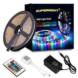
3. SUPERNIGHT LED Strip Lights - 5M/16.4 Ft SMD 3528 RGB 300 LED Color Changing Kit with Flexible Strip Light, 24 Key IR Remote Control, Power Supply
- SUEPRNGIHT 2835 SMD RGB 5M LED strip lights + Remote controller + 12V power supply,non-waterproof , high intensity and reliability, Long lifespan.
- Every 6-LEDS cuttable without damaging the rest strips, according to your requirement.
- Width: 0.8cm, Only Lit Red/Green/Blue,NO White lighting.
- Completely smooth and even light spread, solving the uneven luminous problem with a chain of fluorescent tubes.
- Low carbon, no radiation, no flicker, and no pollution to human and environment. Safe and stable.
Features:
 ▼ Read Reddit mentions
4. uxcell P75-E2 1.3mm Dia 17mm Length Convex Tip Metal Spring Test Probe Pin 100pcs
- Product Name : Test Probe;Model No. P75-E2;Tip Type : ConvexTip
- Tip Size(Approx) : 1.3x1mm/0.05"x0.04"(D*L);Shank Size(Approx) : 1x12.5mm/0.04"x0.5"(D*L)
- Spring Part Size(Not Include Convex Tip Head) : 0.7x2.7mm/0.03"x0.1"(D*L);Overall Length(Approx) : 17mm/0.67"
- Material : Metal;Color : Gold Tone, Silver Tone
- Weight : 9g;Package Content : 100(+/-2%)pcs x Test Probe
Features:
 ▼ Read Reddit mentions
5. EPBOWPT DC 12V 24V to DC 5V 10A, 5V 5A,12V 5A, 10A Power Converter Power Adapter (12/24V to 5V 10A, 12/24V to 5V 10A Converter)
- Convert unstable 12/24V DC power supply into stable 5V 10A DC power output
- Over-voltage, over-current, over-temperature, short-circuit auto protection, and can return to normal conditions in the work
- Essential for car audio system or other 5V car products (particularly useful in vehicles with 24V power supply)
- Input voltage: 12/24V ,Output: 5V/10A
- Widely used in automotive, surveillance systems, railway signals, medical equipment, instruments and meters, LED products, LED strips, cable TV and other low power test systems
Features:
 ▼ Read Reddit mentions
6. Aweking Waterproof DC/DC 12V Step Down to 5V 30A 150W Voltage Buck Converter Regulator Transformer Power Supply for Car Truck Vehicle CE listed
Four Smart Production: embeded Smart Chips provide 4 protection-Overcurrent Protection/Overheated Protection/Short Circuit Protection/High Voltage ProtectionHigh Conversion Efficiecy: Synchronization Rectification Technology-multiple intelligent protection function with high conversion efficiency an...
 ▼ Read Reddit mentions
7. TXINLEI 8586 110V Solder Station, 2 in 1 Digital Display SMD Hot Air Rework Station and Soldering Iron, 12pcs Different Soldering Tips,Solder Wire,Tweezers,Desoldering Pump,700W 480℃
- 【Rework & Soldering】 2 in 1 SMD Hot Air Rework Station and Soldering Iron.
- 【Digital LED Display】 The product adopt microcomputer control,The hot air is digital LED display the temperature.
- 【Solder Station Features】 High power,quick warming-up,Temperature stabilization and is impervious to air,,and long life and low noise. it have inductance in the hadle,it will be quickly to work when you take the handle,when the handle is return to the shelf,the machine will automatic stopage.
- 【Widely Used】 Designed for soldering or de-soldering SOIC, CHIP, QFP, PLCC, BGA and other temperature sensitive components, essential tool for cell phone repair, laptop repair, or circuit boards soldering.
- 【20-in-1 Full Kit】 The packing include: 1 * 8586 Solder station, 12 * Solder iron tips, 1 * 6in1 BGA tools, 1 * Desoldering pump, 1 * 100g solder wire, 2 * Tweezers, 1 * Soldering iron heater, 1 * Hot air gun heater, 1 * IC puller.
Features:
 ▼ Read Reddit mentions
8. DC Power Supply Variable 30V 10A, 4-Digital LED Display, Precision Adjustable Switching Regulated Multifunctional Power Supply Digital with USB Interface, Disply with Output Power Lab Grade
◆【High Precision, Wide Range】LONGWEI DC power supply is a professional power supply regulation device that designed with crystal clear, backlit 4-digit LED display of voltage, current, and power. Precise accuracy: 00.01V and 00.01A. You can easily tune it within 0-30V and 0-10A. Very durable a...
 ▼ Read Reddit mentions
9. IWISS SN-28B Crimping Tool for AWG28-18 Dupont Pins
- Purpose: SN-28B open barrel crimper tool is designed to crimp non-insulated open barrel, OEM-style terminals. Perfect for servo lead connectors and some other RC crimp connectors.
- Capability: 0.1-1.0m㎡, AWG 28-18. Suitable for 2.5mm, 2.54mm, 3.96mm pitch terminals, typically JST VH, XH, NH pins and Dupont 2.54mm connectors.
- Applications: Used to connect electrical wires on rechargeable battery packs, battery balancers, battery eliminator circuits, 3D printers, and radio controlled servos.
- Repetitive, high crimping quality due to precision dies and integral lock (self-releasing mechanism). Ratcheting crimping tool with a 20° angled head. Guaranteed optimal, solderless electrical connections.
- VH 3.96mm Pitch 22-16AWG; RE 2.54mm Pitch 30-24AWG; EH 2.50mm Pitch 32-22AWG; XA 2.50mm Pitch 30-20AWG; XH 2.5mm Pitch 30-20AWG
Features:
 ▼ Read Reddit mentions
10. Amazing Roulette Electric Shocking Gameup to 6 Players 2 Game Modes Finger Shock Party Game
2 interactive and fun game modes (see 2nd picture for further instructions)This shocking game puts a jolt in your partyFun game to play with friendsRequires 3 x AA batteries (not included)Not suitable for children under 6 years of age, adults over 50 years old or persons Under any medical conditions
 ▼ Read Reddit mentions
11. Longruner 5X Geared Stepper Motor 28byj 48 Uln2003 5v Stepper Motor Uln2003 Driver Board with ArduinoIDE (no Wire)
5pcs Stepper motor and driver board compatible with 2560 1280 DSP ARM PIC AVR STM32 Raspberry Pi.Stepper motor with a standard interface. A, B, C, D four-phase LED indicates the status of the stepper motor work.Motor diameter: 1.1 inches.Wire length:9.05 inchs. Stepping angle: 5.625 x 1/64.Reducti...
 ▼ Read Reddit mentions
12. Brisk Links USB 3.0 to HDMI Adapter Converter 1080P HD Display with Audio Support Multi Monitor Adapter - Includes Bonus High Speed HDMI Cable 6 FT (Not Compatible with Mac, Linux)
Drivers Installed Automatically For Windows 10/8/7/XP, Read Included manual for guidnce, Not Compatible With Mac, Linux,Converts USB to HDMI Display Super Speed USB 3.0, With Audio,Supports Audio Function for HDMI Monitor and TVSupports Resolution: up to 1920 x 1080 and video playback to 1080P with ...
 ▼ Read Reddit mentions
13. HDMI to RCA, Electop 1080P Mini HDMI to AV 3 RCA CVBS Converter 1080P Composite Video Audio Converter Adapter Support PAL/NTSC with USB Cable for PC Laptop PS4 HDTV STB VHS VCR Camera -Metal
√ Converting high-quality HDMI video signal to normal CVBS(AV) signal, HDMI Input, Composite Video + Audio R/L Output, available for TV, VHS VCR, DVD recorders, etc.√ Supports NTSC and PAL two standard TV formats with a select switch. You need to select the NTSC format manually before use. Easil...
 ▼ Read Reddit mentions
14. Leviton 102-WP 016-00102-0WP 15 Amp, 125 Volt, Cord outlet, 1 Pack, White
- Brass plug blades and connector contacts for maximum conductivity
- Hinged design for easy wiring
- Plastic devices resist grease, oils and acids
- 2P
- 2W
Features:
 ▼ Read Reddit mentions
15. LED Light Strip, HitLights Neutral White Premium 3528-16.4 Feet, 300 LEDs, 4000K, 550 Lumens/M. UL-Listed. 12V DC Tape Light
- 【HIGH QUALITY LED STRIP LIGHTS】 Use double side PCB 2835 LED lights, it’s more durable and reliable for use. More than 60000Hours(6 Years) lifespan and These discreet strips feature closely packed LEDs for smooth, even light without spotting.
- 【UPGRADED LED TAPE ADHESTIVE】 Compared with other LED strip lights that are not high quality, we use high-quality 3M blue adhesive with heat resistance, strong viscosity and integration. Please contact customer service emails for any LED light strip with adhesive problems. We will solve this problem perfectly!
- 【SIMPLE AND EASY TO USE】Working for 12V voltage, Actual Power Wattage: 24W. Please note that the total wattage of the LED strip should not exceed the maximum wattage of the power adapter. Doing so may cause the LED lights to flicker or the Lights to be dim.
- 【DIMMABLE and FLEXIBLE LED STRIPS】These LED strips are great for a variety of indoor / interior uses including under-cabinet lighting in kitchens ambient accent lighting in bedrooms lighting toekicks in bathrooms or adding a backlighting source to displays decorations or book shelves.
- 【HITLIGHTS QUALITY UL-LISTED】Backed by a SIX year from HitLights for peace of mind. Contact our US-based customer service team at any time for no-hassle troubleshooting and replacement or for any questions about purchasing or installation.
Features:
 ▼ Read Reddit mentions
16. Panasonic K-KJ17MCA4BA Advanced Individual Cell Battery Charger Pack with 4 AA eneloop 2100 Cycle Rechargeable Batteries
- Recharge up to 2100 times
- Maintain up to 70% of their charge after 10 years (when not it use)
- 2000mAh Type, 1900mAh min, Ni-MH pre-charged rechargeable battery
- 4 position charger with advanced, individual battery charging, AA and AAA cells
- Battery detection technology - automatically shuts off when charging is complete
Features:
 ▼ Read Reddit mentions
17. Hongbous Nitecore i2 Intellicharge Charger for 18650 AAA AA Li-Ion/NiMH Battery
Sold on Amazon
 ▼ Read Reddit mentions
18. WeMo (F7C059) Dimmer Wifi Light Switch, Works with Alexa, the Google Assistant and Apple Homekit
- Control and dim lights from anywhere. Only needs Wi-Fi. No Hub or subscription required.
- Control WeMo dimmer from the wall, the WeMo app, or with your voice when paired with Amazon Alexa, the Google Assistant and Apple homekit.
- Syncs with your schedule. Easily set schedules and timers so your lights do what you want when you want. You can even sync lights to adjust with the sunset and sunrise
- Optimize your lights: WeMo dimmer will calibrate to the bulbs you’re using to provide the maximum amount of dimming range with no flickering
- Night mode. Set your WeMo dimmer to your desired low light level and protect your eyes from bright lights
- Note: Works with any 1-way connection light switch (not compatible with 3-way) and requires a neutral wire
- Note: Refer the user manual before use which is highly recommended
Features:
 ▼ Read Reddit mentions
19. Leviton DW3HL-1BW Decora Smart Wi-Fi Plug-In Dimmer, No Hub Required, Works with Alexa and Google Assistant, White
- No Hub: Control your home from anywhere via My Leviton app - simply plug in a lamp and dim or brighten via app, voice, or schedule.
- Capabilities: Schedule lights to adjust when you want including sunrise/sunset, easily create lighting scenes, utilize auto-shutoff feature and vacation (randomization) mode. Easy Wi-Fi lighting for your whole home
- Voice control: Works with Alexa and Google Assistant voice assistants (sold separately). “Alexa, turn floor lamp to 33%.”
- Works with: IFTTT, SmartThings, August, Alexa, Google Assistant and more.
- Very smart: Leviton devices are truly smart – your pre-set schedules live inside each device, so your schedules always run as expected.
- Ratings: Dimmable LED and CFL up to 100W and Incandescent up to 300W. Ideal for table, floor, or hanging lamps to brighten or dim via voice, schedule, or app.
- Leviton: Making your home smarter and safer since 1906. Designed, engineered, and supported in USA with a 5-year limited.
Features:
 ▼ Read Reddit mentions
20. Ginsco 530 Pcs 2:1 Heat Shrink Tubing Tube Sleeving Wrap Cable Wire 5 Color 8 Size with Storage Case
- Supplied internal diameter: 1.5mm, 2mm, 3mm, 4mm, 5mm, 6mm, 8mm, 10mm
- Ratio: 2:1 Operating Temperature: -55°C to + 125°C
- All packed in a plastic container for easy organization and storage.
- Big collection of heat shrink tubing, 5colors, 8 Specifications, 530pcs
Features:
 ▼ Read Reddit mentions
Top comments mentioning products on r/diyelectronics:
Summary
1. Make: Electronics: Learning Through Discovery
- New
- Mint Condition
- Dispatch same day for order received before 12 noon
- Guaranteed packaging
- No quibbles returns
Features:
▼ Read Reddit mentions2. DROK 091016 DC-DC Buck Converter 4-38V Step-down Voltage Regulator Module Adjustable Current 5A Max 75W High Power Volt Power Supply Transformer Board with Constant Current & Voltage
- Limited-current/short-circuit/over-temperature/input reversed connection protection all allows safe usage
- Work as buck converter, high-power LED constant amp driving module and battery charger with USB connector
- With two working modes of constant volt and constant amp which would be indicated by the RED LED indicator
- Can set float volt&charging amp if being used as lithium battery charger with green LED lights in full-charge
- A large area of copper in its back to strengthen heating radiating; low ripple, high efficiency and large power
Features:
▼ Read Reddit mentions3. SUPERNIGHT LED Strip Lights - 5M/16.4 Ft SMD 3528 RGB 300 LED Color Changing Kit with Flexible Strip Light, 24 Key IR Remote Control, Power Supply
- SUEPRNGIHT 2835 SMD RGB 5M LED strip lights + Remote controller + 12V power supply,non-waterproof , high intensity and reliability, Long lifespan.
- Every 6-LEDS cuttable without damaging the rest strips, according to your requirement.
- Width: 0.8cm, Only Lit Red/Green/Blue,NO White lighting.
- Completely smooth and even light spread, solving the uneven luminous problem with a chain of fluorescent tubes.
- Low carbon, no radiation, no flicker, and no pollution to human and environment. Safe and stable.
Features:
▼ Read Reddit mentions4. uxcell P75-E2 1.3mm Dia 17mm Length Convex Tip Metal Spring Test Probe Pin 100pcs
- Product Name : Test Probe;Model No. P75-E2;Tip Type : ConvexTip
- Tip Size(Approx) : 1.3x1mm/0.05"x0.04"(D*L);Shank Size(Approx) : 1x12.5mm/0.04"x0.5"(D*L)
- Spring Part Size(Not Include Convex Tip Head) : 0.7x2.7mm/0.03"x0.1"(D*L);Overall Length(Approx) : 17mm/0.67"
- Material : Metal;Color : Gold Tone, Silver Tone
- Weight : 9g;Package Content : 100(+/-2%)pcs x Test Probe
Features:
▼ Read Reddit mentions5. EPBOWPT DC 12V 24V to DC 5V 10A, 5V 5A,12V 5A, 10A Power Converter Power Adapter (12/24V to 5V 10A, 12/24V to 5V 10A Converter)
- Convert unstable 12/24V DC power supply into stable 5V 10A DC power output
- Over-voltage, over-current, over-temperature, short-circuit auto protection, and can return to normal conditions in the work
- Essential for car audio system or other 5V car products (particularly useful in vehicles with 24V power supply)
- Input voltage: 12/24V ,Output: 5V/10A
- Widely used in automotive, surveillance systems, railway signals, medical equipment, instruments and meters, LED products, LED strips, cable TV and other low power test systems
Features:
▼ Read Reddit mentions6. Aweking Waterproof DC/DC 12V Step Down to 5V 30A 150W Voltage Buck Converter Regulator Transformer Power Supply for Car Truck Vehicle CE listed
Four Smart Production: embeded Smart Chips provide 4 protection-Overcurrent Protection/Overheated Protection/Short Circuit Protection/High Voltage ProtectionHigh Conversion Efficiecy: Synchronization Rectification Technology-multiple intelligent protection function with high conversion efficiency an...
▼ Read Reddit mentions7. TXINLEI 8586 110V Solder Station, 2 in 1 Digital Display SMD Hot Air Rework Station and Soldering Iron, 12pcs Different Soldering Tips,Solder Wire,Tweezers,Desoldering Pump,700W 480℃
- 【Rework & Soldering】 2 in 1 SMD Hot Air Rework Station and Soldering Iron.
- 【Digital LED Display】 The product adopt microcomputer control,The hot air is digital LED display the temperature.
- 【Solder Station Features】 High power,quick warming-up,Temperature stabilization and is impervious to air,,and long life and low noise. it have inductance in the hadle,it will be quickly to work when you take the handle,when the handle is return to the shelf,the machine will automatic stopage.
- 【Widely Used】 Designed for soldering or de-soldering SOIC, CHIP, QFP, PLCC, BGA and other temperature sensitive components, essential tool for cell phone repair, laptop repair, or circuit boards soldering.
- 【20-in-1 Full Kit】 The packing include: 1 * 8586 Solder station, 12 * Solder iron tips, 1 * 6in1 BGA tools, 1 * Desoldering pump, 1 * 100g solder wire, 2 * Tweezers, 1 * Soldering iron heater, 1 * Hot air gun heater, 1 * IC puller.
Features:
▼ Read Reddit mentions8. DC Power Supply Variable 30V 10A, 4-Digital LED Display, Precision Adjustable Switching Regulated Multifunctional Power Supply Digital with USB Interface, Disply with Output Power Lab Grade
◆【High Precision, Wide Range】LONGWEI DC power supply is a professional power supply regulation device that designed with crystal clear, backlit 4-digit LED display of voltage, current, and power. Precise accuracy: 00.01V and 00.01A. You can easily tune it within 0-30V and 0-10A. Very durable a...
▼ Read Reddit mentions9. IWISS SN-28B Crimping Tool for AWG28-18 Dupont Pins
- Purpose: SN-28B open barrel crimper tool is designed to crimp non-insulated open barrel, OEM-style terminals. Perfect for servo lead connectors and some other RC crimp connectors.
- Capability: 0.1-1.0m㎡, AWG 28-18. Suitable for 2.5mm, 2.54mm, 3.96mm pitch terminals, typically JST VH, XH, NH pins and Dupont 2.54mm connectors.
- Applications: Used to connect electrical wires on rechargeable battery packs, battery balancers, battery eliminator circuits, 3D printers, and radio controlled servos.
- Repetitive, high crimping quality due to precision dies and integral lock (self-releasing mechanism). Ratcheting crimping tool with a 20° angled head. Guaranteed optimal, solderless electrical connections.
- VH 3.96mm Pitch 22-16AWG; RE 2.54mm Pitch 30-24AWG; EH 2.50mm Pitch 32-22AWG; XA 2.50mm Pitch 30-20AWG; XH 2.5mm Pitch 30-20AWG
Features:
▼ Read Reddit mentions10. Amazing Roulette Electric Shocking Gameup to 6 Players 2 Game Modes Finger Shock Party Game
2 interactive and fun game modes (see 2nd picture for further instructions)This shocking game puts a jolt in your partyFun game to play with friendsRequires 3 x AA batteries (not included)Not suitable for children under 6 years of age, adults over 50 years old or persons Under any medical conditions
▼ Read Reddit mentions11. Longruner 5X Geared Stepper Motor 28byj 48 Uln2003 5v Stepper Motor Uln2003 Driver Board with ArduinoIDE (no Wire)
5pcs Stepper motor and driver board compatible with 2560 1280 DSP ARM PIC AVR STM32 Raspberry Pi.Stepper motor with a standard interface. A, B, C, D four-phase LED indicates the status of the stepper motor work.Motor diameter: 1.1 inches.Wire length:9.05 inchs. Stepping angle: 5.625 x 1/64.Reducti...
▼ Read Reddit mentions12. Brisk Links USB 3.0 to HDMI Adapter Converter 1080P HD Display with Audio Support Multi Monitor Adapter - Includes Bonus High Speed HDMI Cable 6 FT (Not Compatible with Mac, Linux)
Drivers Installed Automatically For Windows 10/8/7/XP, Read Included manual for guidnce, Not Compatible With Mac, Linux,Converts USB to HDMI Display Super Speed USB 3.0, With Audio,Supports Audio Function for HDMI Monitor and TVSupports Resolution: up to 1920 x 1080 and video playback to 1080P with ...
▼ Read Reddit mentions13. HDMI to RCA, Electop 1080P Mini HDMI to AV 3 RCA CVBS Converter 1080P Composite Video Audio Converter Adapter Support PAL/NTSC with USB Cable for PC Laptop PS4 HDTV STB VHS VCR Camera -Metal
√ Converting high-quality HDMI video signal to normal CVBS(AV) signal, HDMI Input, Composite Video + Audio R/L Output, available for TV, VHS VCR, DVD recorders, etc.√ Supports NTSC and PAL two standard TV formats with a select switch. You need to select the NTSC format manually before use. Easil...
▼ Read Reddit mentions14. Leviton 102-WP 016-00102-0WP 15 Amp, 125 Volt, Cord outlet, 1 Pack, White
- Brass plug blades and connector contacts for maximum conductivity
- Hinged design for easy wiring
- Plastic devices resist grease, oils and acids
- 2P
- 2W
Features:
▼ Read Reddit mentions15. LED Light Strip, HitLights Neutral White Premium 3528-16.4 Feet, 300 LEDs, 4000K, 550 Lumens/M. UL-Listed. 12V DC Tape Light
- 【HIGH QUALITY LED STRIP LIGHTS】 Use double side PCB 2835 LED lights, it’s more durable and reliable for use. More than 60000Hours(6 Years) lifespan and These discreet strips feature closely packed LEDs for smooth, even light without spotting.
- 【UPGRADED LED TAPE ADHESTIVE】 Compared with other LED strip lights that are not high quality, we use high-quality 3M blue adhesive with heat resistance, strong viscosity and integration. Please contact customer service emails for any LED light strip with adhesive problems. We will solve this problem perfectly!
- 【SIMPLE AND EASY TO USE】Working for 12V voltage, Actual Power Wattage: 24W. Please note that the total wattage of the LED strip should not exceed the maximum wattage of the power adapter. Doing so may cause the LED lights to flicker or the Lights to be dim.
- 【DIMMABLE and FLEXIBLE LED STRIPS】These LED strips are great for a variety of indoor / interior uses including under-cabinet lighting in kitchens ambient accent lighting in bedrooms lighting toekicks in bathrooms or adding a backlighting source to displays decorations or book shelves.
- 【HITLIGHTS QUALITY UL-LISTED】Backed by a SIX year from HitLights for peace of mind. Contact our US-based customer service team at any time for no-hassle troubleshooting and replacement or for any questions about purchasing or installation.
Features:
▼ Read Reddit mentions16. Panasonic K-KJ17MCA4BA Advanced Individual Cell Battery Charger Pack with 4 AA eneloop 2100 Cycle Rechargeable Batteries
- Recharge up to 2100 times
- Maintain up to 70% of their charge after 10 years (when not it use)
- 2000mAh Type, 1900mAh min, Ni-MH pre-charged rechargeable battery
- 4 position charger with advanced, individual battery charging, AA and AAA cells
- Battery detection technology - automatically shuts off when charging is complete
Features:
▼ Read Reddit mentions17. Hongbous Nitecore i2 Intellicharge Charger for 18650 AAA AA Li-Ion/NiMH Battery
Sold on Amazon
▼ Read Reddit mentions18. WeMo (F7C059) Dimmer Wifi Light Switch, Works with Alexa, the Google Assistant and Apple Homekit
- Control and dim lights from anywhere. Only needs Wi-Fi. No Hub or subscription required.
- Control WeMo dimmer from the wall, the WeMo app, or with your voice when paired with Amazon Alexa, the Google Assistant and Apple homekit.
- Syncs with your schedule. Easily set schedules and timers so your lights do what you want when you want. You can even sync lights to adjust with the sunset and sunrise
- Optimize your lights: WeMo dimmer will calibrate to the bulbs you’re using to provide the maximum amount of dimming range with no flickering
- Night mode. Set your WeMo dimmer to your desired low light level and protect your eyes from bright lights
- Note: Works with any 1-way connection light switch (not compatible with 3-way) and requires a neutral wire
- Note: Refer the user manual before use which is highly recommended
Features:
▼ Read Reddit mentions19. Leviton DW3HL-1BW Decora Smart Wi-Fi Plug-In Dimmer, No Hub Required, Works with Alexa and Google Assistant, White
- No Hub: Control your home from anywhere via My Leviton app - simply plug in a lamp and dim or brighten via app, voice, or schedule.
- Capabilities: Schedule lights to adjust when you want including sunrise/sunset, easily create lighting scenes, utilize auto-shutoff feature and vacation (randomization) mode. Easy Wi-Fi lighting for your whole home
- Voice control: Works with Alexa and Google Assistant voice assistants (sold separately). “Alexa, turn floor lamp to 33%.”
- Works with: IFTTT, SmartThings, August, Alexa, Google Assistant and more.
- Very smart: Leviton devices are truly smart – your pre-set schedules live inside each device, so your schedules always run as expected.
- Ratings: Dimmable LED and CFL up to 100W and Incandescent up to 300W. Ideal for table, floor, or hanging lamps to brighten or dim via voice, schedule, or app.
- Leviton: Making your home smarter and safer since 1906. Designed, engineered, and supported in USA with a 5-year limited.
Features:
▼ Read Reddit mentions20. Ginsco 530 Pcs 2:1 Heat Shrink Tubing Tube Sleeving Wrap Cable Wire 5 Color 8 Size with Storage Case
- Supplied internal diameter: 1.5mm, 2mm, 3mm, 4mm, 5mm, 6mm, 8mm, 10mm
- Ratio: 2:1 Operating Temperature: -55°C to + 125°C
- All packed in a plastic container for easy organization and storage.
- Big collection of heat shrink tubing, 5colors, 8 Specifications, 530pcs
Features:
▼ Read Reddit mentions
> I don't know, maybe that's its intended function, as I said, it works, but I'm a bit afraid that it will drain the four AA batteries pretty fast, and could possibly damage rechargable ones by too much current draw.
>
> Yes, I do have a multimeter. A sticker at the back rates the radio for 6V and 4w (as far as my understanding of russian goes)
4 watts is an enormous amount of power to draw from 4 modestly antique alkaline AA batteries in a receive-only radio. However, it's not too much, especially for rechargeable AA batteries. You just have to avoid fully discharging them to extend their life. You can do that by timing how long it takes to fully discharge, then cut that time in half, and charge your AA batteries at the halfway point. I'm guessing you will only get a few minutes of run time.
You will also need a smart charger that won't overcharge half-discharged AA batteries with a full charge. Might as well get good AA batteries too, because the best charger comes with them. I recommend you get these ones (make sure your battery specifications match the packaging in this photo):
Get this package first to get the highest quality charger on the market:
> A nice -dv/dt termination with only a small temperature increase and no trickle charge, this looks very good. [...] The charger is very good at filling the batteries.
You need that charger to get the full life out of Eneloops. If you take care of them, Eneloops will last at least a decade, maybe longer. They achieve maximum longevity when you charge before they reach 60% depth of discharge (40% remaining capacity). So, if you charge them at the half discharged point (50% remaining capacity), that's a convenient even number, and a bit better than the ideal.
WALL OF TEXT ALERT:
The most difficult part of building a proper charger for an 18650 bank will be to ensure that the charge system will be able to balance each battery/cell during charging. You can find a lot of single cell charging solutions at sparkfun. The only thing is that product is only meant to handle a single cell. You could run one of those charging boards for each cell but I could see that being pretty bulky.
You specified that you want the bank to be 12 V with a capacity of 50 Ah. The nominal voltage for an 18650 is 3.7 V but fully charged is 4.2 V. That would mean that you want 4 batteries in series to ensure > 12 V during use while they drain down to 3.7 V each before needing a recharge (This is assuming that your output regulator does not have a boost on it). To achieve the 50 Ah mark you will need a total of 17 batteries (or 16 for a capacity of 48 Ah if the 50 Ah is not a strict requirement). That would need that you need 4 sets in parallel of 4 batteries in series (If that makes sense). I would go for the 4 sets of 4 to keep the parallel sub-groups of the system symmetric and balanced during discharges. You will definitely need some regulation out of the battery bank for the devices you want to charge. Probably a 12 V out and a 5 V out for various devices. This also assumes that the batteries internal behaviors during discharge will let every set of batteries discharge all at the same rates, which will probably not perfectly be the case.
Like I said, the most difficult part of this build will be making the charging side be able to balance the cells during charge. It might be easier to just get a hold of a 4 cell 18650 balance charger, unplug the batteries from your system, and charge the batteries in a pre-made charging system. For the most optimal charge times you would want 4 of those chargers so you can charge each parallel group at the same time. Something like this.
I did find this charging PCB on EBay that could be built into your bank with the input pads all soldered in parallel for each sub-bank of batteries (Make sure the wiring can handle more than 12 A or bundle 4 sets of wires together that can handle 3 A each). The board is rated for a maximum current of 3 A meaning that to charge 4 batteries up to 3000 mAh (3 Ah) would take roughly 4 hours for each sub-group of cells. The big charger would definitely charge each set of batteries much quicker, but would be a separate system from your charger bank.
Keep in mind that everything I've discussed was just a quick breakdown of the difficult parts that I can see right now. I'm not 100% sure what kind of output rails you want to build or the currents you want to be able to run out of the bank. I tried to focus mainly on the charging portion of the project. Since LiPos need a proper charging system to keep the batteries healthy over long periods of use and each cell needs to be balanced for everything to remain in spec over the duration of the life of system any charging system needs to be able to perform proper balanced charging to each cell.
Let me know if you have any other questions or are looking for any particular out-of-box solution for any piece of the project. Something like this could be very useful to have, but you definitely want to make sure that the batteries will be properly handled to ensure longer lifetimes.
Oh wow, I have non-24 and not very much money, so I've actually been working on doing basically the same thing! Right now I have some fluorescent grow lights plugged into a wemo switch, and let me tell you..... it's certainly not the same.
The bad news is that from what I can find, there's no real good way to do it cleanly if you want dimming, since most smart plugs are a simple binary on/off. I have found a few options though!
(I'm sure you know but please note the requisite be super careful around AC voltage, it'll make you dead)
The first is something along the lines of this, what's meant to be an in-wall dimmer to replace a 1-gang light switch. That's probably gonna be the easiest way to do it -- just attach it to the wires in-line, and you're good to go. There are other, similar options that may be cheaper, especially if you can use something like z-wave.
I don't have a link atm, but I also know that I've seen someone take a normal cheapo wall dimmer and just... hook a lil servo motor up to it. That's also an option?
After some searching, I did find what seems to be the one plug-in smart dimming outlet that doesn't require a hub. Heads-up though, it's only rated to 100W with LEDs so you'll wanna be careful. Not having look much into this, I make no promises, but my cursory googling actually seems really promising. Price isn't horrible, either.
So here's where I thought to check the wonderful world of Sonoff. It's not the CLEANEST solution visually, but they actually do make a smart socket -- if you're willing to drop $60 and be done, just get six of these guys here.
EDIT: Just kidding, those bases also do not have dimmers, so they won't work. But here's a video of someone using one of their surprisingly cheap wall dimmers to do just what you want!
You'll want to connect them to each other like this.
You could solder them directly together, but I'd suggest using wires between them; solder one of the wire to one board, and the other side of the wire to the other board.
You could use electrical tape over the solder junctions to insulate them (instead of heat shrink), but make sure you wind the tape snugly and use at least 3 layers of tape around each junction. Here's an example kit of heat shrink. It's not expensive, and is rather easy to use. video of how to use shrink tube. Video on using a hair dryer in case you don't have a heat gun. If you don't have a heat gun or hair dryer, then heat shrink probably isn't a good option for you at this time.
For the capacitor and the wiring connections, don't follow the diagram verbatim. If one wire touches a bunch of other wires, it doesn't matter WHERE they touch, only THAT they touch. So, in theory, you could have one long "main" wire and solder other wires onto it separately one at a time along the entire length of the "main" wire, or you could just wire the ends of all the wires at one single spot, or "junction". Either way has the same effect - all the wires are ultimately touching. See how the capacitor is connected to the red and black wires? You could solder it at any point on either of those wires. So it could go right on top of the end of the neopixel strand, or right on top of the arduino, anywhere that you think would work well for how you're assembling this thing. If you're using a breadboard (i suggest this) and want the easiest option, you could plug it right into there and not worry having to actually solder it to anything. If you want a "best practices" opinion, it would be ideal to solder it right into the end of the neopixel strand.
Since you're using multiple neopixel strands, It might be best to use one of these capacitors in between each strand in a similar fashion. I'm not sure how much this would actually matter, though. Just kind of a safe vs sorry thing, I guess. One capacitor is probably fine.
By the way, on my diagram, I used pins 6 and 11 as examples. You can use any pin with an "A" (A0 thorugh A7) for the potentiometer, any PWM pin (3, 5, 6, 9, 10, or 11) for the neopixel output, and any pin with a "normal" number (2 through 13) for the pushbutton. Info on arduino pins.
More info on Arduino Pro pins, etc
This basic remote that comes with LED strips usually:
https://www.amazon.com/SUPERNIGHT-Changing-Flexible-Remote-Control/dp/B00BP4DUMU?ref_=fsclp_pl_dp_3
The battery is fine and it works but I realy want to be able to point it in different angles and still be able to use it because no I need to be 1m or closer and aim dirrectly to it and the reciever is in pretty uncomfortable spot so I have to walk there everytime and put my hand behind shelf to change colors. Maybe I can modify the remote and/or reciever to be able to do it from ~5m and in different angles too? I understand that I cant point the remote away and hope that it will work but cmon I can't be wrong by 0.5 degrees now if I want it to work now....
K I am bit oversaturating but I realy want to upgrade it a bit XD
Thanx
Arduino is great for plug and play, blink an LED, using code. But if you want to understand electronics I would start here:
Easy Electronics (Make: Handbook) https://www.amazon.com/dp/168045448X/
^you could shoot through this book in a weekend.
After doing that book I would get this book:
Make: Electronics: Learning Through Discovery https://www.amazon.com/dp/1680450263/
You can purchase the parts individually or buy kits specifically made for the books. I found the kits will save you time.
I started like you a few years ago and now have moved on to arduino and am designing my own PCBs. Good luck.
I would drill holes in a stiff material to line them up to meet your designs specifications, and use something like a "metal test probe pin," or pogo pin, to align the legs individually. I use this method, and it helps me out quite effectively. Amazon link: https://www.amazon.com/Uxcell-a15091500ux0390-P75-E2-Convex-Diameter/dp/B018YPQ6ZK/ref=sr_1_5?ie=UTF8&qid=1543465361&sr=8-5&keywords=pogo+pins But anything small and cylindrical will do the job of moving the legs of the pot for your needs without compromising the legs enough to break on you. I hope this helps you; it works for me. Cheers
> I'm just wondering what would be the best method for the dc 2 dc conversion, I also want to ensure the circuit can handily cope with any sudden surges in demand, while maintaining a clean and stable 5v supply.
I like the laptop PSU idea. I do that in my projects sometimes.
You may want to consider having more PSU headroom to avoid running near max capacity for your 5V reg. I snooped around and found this item. It delivers 10A from 12-24 VDC. What I can't find is a decent set of specs to give the Power Out noise (ripple). I like my 5V ultra quiet.
Envy you the PI4 BTW. Would you please tell me your RAM size and performance browsing the web? My PI3-1GB barely makes it for web browsing.
hth
I'm using the 4GB and even with raspbian it fair zips along, I'm running with root on a usb ssd (careful not all usb3 -> sata are compatible) and that does make a difference, a 240 sdd can be cheaper than and expensive 32gb sd card and much faster... It certainly has enough power to browse the web the pi2 was torture by comparison! chromium loads in around 2-4 seconds, and feels just like its on a fairly standard laptop!
re: this Will this require some kind of heat sink, I'd prefer something as efficient as possible, I'm wondering if it might need a set of different valued capacitors on the output to help with ripple, I do have a modest oscilloscope so I should be able to see how horrid the ripple or takeup looks like I am wondering what would happen when there is sudden cpu load applied and the governor switches all 4 cores from 600hmz to 1.5ghz....!
I was a little dubious about the claims attached to the Pi4 but was pleasantly surprised, you could certainly use it as I've set mine up (root on ssd, etc), as a "daily driver"
You may be able to do something like this:
Use an RC/Drone LiPo battery: https://www.hobbyzone.com/batteries/lipo/4-cell/ONXP2459.html
Connect it to a switching Dc-Dc converter: https://www.amazon.com/dp/B06X1DPFQQ/
Now you have 5V, 30A available for your LEDs. Note, things will get HOT running at full power, you'll need a way to cool down the LEDs and the Dc-Dc converter.
Using that battery (75 watt hours), you should be able to power your LEDs (150watts) for about half an hour at full brightness.
Also, Id be very careful working with high capacity Lipo batteries, do your research and take precautions, they can be dangerous if not used correctly (shorting out leads/puncturing the case etc).
You may be able to find a better quality Dc-Dc converter, but make sure its a switching converter as they are much more energy efficient compared to a linear regulator Dc-Dc. 3 of these could also work: https://www.amazon.com/dp/B00VUHVX6W/
Edit: I just realize you need 4 (not 3) * 5V/10A, or 200W power.
Yeah, avoid anything that says gun. Soldering guns often don't have isolated tips and are too big for hobby soldering unless you really need the power for huge wires and chasis mount stuff like Nico said. Even if you are working with heavier stuff you can pre-heat with a hotair tool and finish the soldering up with the iron.
Here's a link for reference on the kind of rework station Nico is talking about.
https://www.amazon.com/TXINLEI-8586-Soldering-Different-Desoldering/dp/B07FJ6PNHF/
You can find cheaper one's off AliExpress or ebay but much bellow about 60 dollars and you're going to sacrifice basic quality and saftey. A lot of the super cheap kits don't have ground properly wired inside, if you decide to get one make sure you open the unit up and take a peak inside to ensure that it's grounded properly.
I completely agree with the choices and the Arduino statement as so many electronics beginners want to jump right in to Arduino and microcontroller usage without having any base electronics knowledge which is really required to use them properly.
​
That is one reason the 2nd Edition of Make: Electronics stands out as the better choice IMO if your only buying 1 book as it starts out with very basic circuits, gets you the fundamentals, and the progresses all the way up through Arduino usage at the end in the last few experiments. Their are also some premade kits the author suggests for the book. They are a bit pricey but they make it a lot easier for the beginner to have all of the correct parts on hand and sorted while reading each experiments.
​
Book: https://www.amazon.com/dp/1680450263
Kits: https://www.protechtrader.com/Make-electronics-component-pack-1-2nd-edition
​
​
If you don't have any documentation on the device to determine its power consumption, get a cheap switching DC bench power supply and you can measure how much power the device will draw. You will need to know at least what voltage the device is expecting because overvolting will likely damage it.
You can get a bench power supply that does from 0-30V at up to 5A draw for as low as 60$ on amazon. I got one that does 0-30V up to 10A for about $120.
Here is the one I bought:
https://www.amazon.com/gp/product/B07ML2MP9Q
Attach the lab power supply as the power source, then turn the voltage knob until until the voltage matches whatever the specs indicate (be careful not to overvolt). Turn on the device and the digital readout will tell you how much it is drawing in amps. Take that reading and buy a power supply adapter with 10-20% more to handle spikes in draw that might occur.
Note that "wattage" is just the amps*voltage, so if was at 24V and the readout showed it was consuming 2A, then that would be 48W and buying a 24V 60W power adapter would likely be enough. You can always go higher on the wattage/amps as long as the voltage is correct. Devices will draw what they need, the power adapter wont send more, etc. So, given the example above, buying a 24V 100W adapter would be overkill and likely be more expensive, but it wouldn't damage anything. This is why its great to save old power adapters from laptops and toys as they can be reused in many cases.
Another option to measure draw is to start with a power adapter that provides more than enough wattage, put a voltmeter in series with the circuit and measure the current with the voltmeter. You do have to make sure that the voltmeter you are using is fused for the upper end of your expected current draw. Most multimeters have two current options, a very low current one and a 10A one. The terminals will be labeled as such.
I bought this one and some random bits for it (not sure what they're called, maybe pin housing?), and everything works great.
$23 isn't bad. The end result is worth it, and it's much faster than soldering for me
You buy the $25 ratcheting ones from amazon.
I have some $600 - $900 crimpers, but DuPont like in the picture doesn’t require it.
There’s a lot of skill involved with it, don’t solder your wires to the pins, take the time and get good with them.
IWISS SN-28B Crimping Tool for AWG28-18 Dupont Pins https://www.amazon.com/dp/B00OMM4YUY/ref=cm_sw_r_cp_api_i_eKYSDb81BFEFY
Assuming you define a smart charger as a charger capable of charging individual cells in a pack evenly and expeditiously I would say it's not required. OP can purchase a less expensive battery protection circuit ("BPC") or protected cells (18650s with the BPC built in) and lower his charge rate to a meager amount -- but even a 1A charge rate would be fine and charge the pack in ~4 hours. The inexpensive replacement for the smart charger would then be a constant current regulator. There are lots of versions of these, some with both a voltage and current display, and of course they can be dirt cheap when purchased from your friendly Chinese reseller.
I'm not saying your answer is wrong I'm just throwing it out there as another option.
Current will be self-limited by the boost controller I would think.
How hard do these shock people, do you know? Shocking people is pretty easy. You could just re-use something like this: https://www.amazon.com/Amazing-Roulette-Electric-Shocking-Game/dp/B07HYJPLC6/
https://www.aliexpress.com/item/33007353192.html
This might be bass-ackward but you could rig a small peristaltic pump to draw 5ml of water from the tank into a test tube, and another to drip-in the usual chemical test kit solution, then a webcam (or other optical sensor) to compare the color and produce a digital result. After testing, you would need to tip and flush the test tube a couple of times. It sounds like you would need 3 stepper motors, and these $2 ones might do the trick: https://www.amazon.com/Longruner-Stepper-Uln2003-arduino-LK67/dp/B015RQ97W8/ref=sr_1_4?keywords=stepper+motors&qid=1557919422&s=electronics&sr=1-4
​
There are plans on Thingiverse for 3D-printed peristaltic pumps made from stepper motors and skate bearings.
Could you instead record the video, in SW convert the file into side-by-side, and then output over two composite outputs?
​
I.e, use the existing HDMI port, find an HDMI-composite converter, and that powers the first screen. The second screen needs a USB-HDMI+HDMI-composite or USB-composite converter. When the video is played back, it's expanded such that half is on the left and half is on the right.
​
https://www.amazon.com/Brisk-Links-Converter-Adapter-Display/dp/B078X4Z1X2/
​
2x of https://www.amazon.com/Electop-Converter-Composite-Adapter-Supporting/dp/B07BVPV466/
​
(No idea how good these products are).
​
Some solid recommendations, these 2 books:
Forrest Mims: Getting Started in Electronics
Buy it: https://www.amazon.com/dp/0945053282/ref=cm_sw_r_cp_apa_i_MYa-AbTX971NC
Free to view or download here:
https://www.scribd.com/doc/19963886/Forrest-Mims-III-Getting-Started-in-Electronics-Radio-Shack
Make: Electronics: Learning Through Discovery
Buy it: https://www.amazon.com/dp/1680450263/ref=cm_sw_r_cp_apa_i_kZa-AbGYCSCM1
Also (arduino is great; but if you work through these books a little bit first you will be light years ahead when you start with arduino having learned the core concepts)
Checkout the Make: Electronics book by Charles Platt as their are quality electronics kits for them and should be exactly what you looking for as they start out with beginner circuits on breadboards and move on to soldering PCBs and even has some microcontroller programming projects at the end on a Arduino. The author recommends some component packs designed to follow the book on his site I'll link below that are complete and well done. I have used the book and kits myself and suggested them for a few others looking for similiar thing and never had a complaint about them.
Careful though as the Chaney kits do not cover the whole book, only the Protechtrader ones do as the authors site mentions
http://www.plattkits.com
https://www.amazon.com/ProTechTrader-Make-Electronics-Component-Educational/dp/B01EKO6FYQ
https://www.protechtrader.com/Make-electronics-component-pack-1-2nd-edition
https://www.amazon.com/Make-Electronics-Learning-Through-Discovery/dp/1680450263
It's that simple.
The switch is a 3-way switch, and they would typically either use 30/60/90 watt or 50/100/150 watt bulbs. Probably the former in this case.
If you go with LED lights, they take only about 3 watts per string, and the switch will handle that easily.
You need a plug like this:
https://www.amazon.com/Leviton-102-WP-016-00102-0WP-Outlet-White/dp/B000H5WIR6
Cut off the current bulb, wire in that socket, and you'll be golden.
Yeah looks like a 3528 chip so..https://www.amazon.com/HitLights-Neutral-Premium-3528-16-4-UL-Listed/dp/B01A79H4GQ/ref=sr_1_39?keywords=3528+led&qid=1557059842&s=gateway&sr=8-39
Cheaper on ebay:https://www.ebay.com/itm/Red-Blue-Green-RGB-RGBW-5m-10m-3528-5050-150-300-600-LED-Strip-Light/222114743006?hash=item33b71202de:m:m8r24OzTRDL9FJEgmLGYh2g
If what your putting it in has any type of heatsink you can go with a higher power chip, but you need to look at your power supply etc.
​
https://www.dhresource.com/0x0s/f2-albu-g1-M01-F8-74-rBVaGVY9oc2ABAzRAAJZcqvm28k012.jpg/led-strips-kit-5630-5050-3528-smd-60led-led.jpg