(Part 2) Reddit mentions: The best electric motors
We found 378 Reddit comments discussing the best electric motors. We ran sentiment analysis on each of these comments to determine how redditors feel about different products. We found 192 products and ranked them based on the amount of positive reactions they received. Here are the products ranked 21-40. You can also go back to the previous section.
21. OEM Upgraded Carrier Bryant Payne 1/4 HP 230v Condenser Fan Motor HC39GE237
BRAND NEW OEM Upgraded Condenser Fan Motor1/4 HP, 208-230 VoltOEM Wiring Color Code Makes Wiring Easy!

Specs:
| Height | 10 Inches |
| Length | 8 Inches |
| Weight | 9.92 Pounds |
| Width | 6 Inches |
| Number of items | 1 |
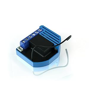
22. Qubino Z-Wave Plus Universal Relay with Dry Contact Switch ZMNHND3
WHAT DOES IT DO? Install it behind your push-button garage opener switch, or at the low-voltage installation for your fireplace, or any dry contact circuit to get on/off Z-Wave control and status updates to your smart home hub.WHAT ELSE DO I NEED? Check for NEUTRAL wire in the switch box (VERY IMPOR...
Specs:
| Height | 1.574803148 Inches |
| Length | 0.393700787 Inches |
| Width | 1.574803148 Inches |
23. Hallmark Industries MD0510A DC Motor, 1hp, 1750 RPM, 90 VDC, 56C, TEFC, with Foot
- Made in China
- Package height :39.37 cm
- Package length :19.304 cm
- Package width :22.86 cm
Features:

Specs:
| Release date | April 2018 |
| Size | TEFC, 24V, 3/4HP |
| Number of items | 1 |
24. Thermaltake RIING 140mm Blue LED Ultra Quiet High Airflow Computer Case Fan, Twin Pack CL-F048-PL14BU-A
- Twin Pack x 140mm Blue LED Computer Case/ Radiator Fans
- Noise Reduction Level by 24% from 24.6 dBA to 18.7 dBA.
- High Airflow: 12/14 40.6/51.1CFM.
- Concentrated Compression Blade: the CCB is engineered to focus the inner weaker circle of air outwards, allowing the outer section to pressurize and compress the air.
- Anti-vibration Mounting System: In-mold injection anti-vibration rubber pads provide hassle-free usage for 80% protection coverage, including all four corners.
- 3 years warranty
Features:

Specs:
| Color | Blue |
| Height | 2 Inches |
| Length | 7 Inches |
| Weight | 0.5 Pounds |
| Width | 5 Inches |
| Size | 140mm |
25. uniquegoods AC 220V 80A 10000W High Power Digital SCR PWM Motor Speed Controller Voltage Regulator Dimming Control Attemperation Thermoregulation
Parameter: Use voltage: AC 220V. Maximum power: 10000W.Voltage regulation: 0-100% (220 volts, 100-level adjustment, non-linear).Features: Using the new two-way high-power SCR, max current up to 80A.The voltage regulator with the peak voltage absorption circuit effectively protects the high-power SCR...

Specs:
| Weight | 0.2 Pounds |
26. Nema 34 Stepper Motor 6A 12Nm (1700 oz-in) 156mm Length for CNC Router Mill Lathe
- Nema 34 156mm length stepper motor.
- Holding Torque: 12Nm (1700oz.in)
- Weight: 5.2kg
Features:

Specs:
| Color | Black |
| Weight | 11.464037624 Pounds |
27. uxcell DC 12V 1000RPM Micro Speed Reduction Motor Mini Gear Box with 2 Terminals for RC Car Robot Model DIY Engine Toy
- 3D printer motor with high torque
- 59Ncm(83.6oz.in) holding torque
- NEMA 17 bipolar 1.65"x1.65"x1.89" 4-wire
- Build with 39.37"( 1m) Cable and 0.1" pitch Connector
- Rated current 2.0A & resistance 1.4ohms
Features:

Specs:
| Height | 0.39 Inches |
| Length | 1.42 Inches |
| Width | 0.47 Inches |
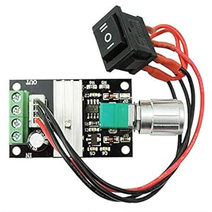
28. uniquegoods 6V 12V 24V 28V 3A 80W DC Motor Speed Controller (PWM) Speed Adjustable Reversible Switch 1203BB DC Motor Driver Reversing
Package:1 x dc motor speed controllerItem size: 1.3*2*0.4 inches; Net Weight:1.13 ouncesDuty Cycle adjustable: 5%-100%, potentiometer with switch function.The maximum output power: 80WThe maximum continuous output current :3A
Specs:
| Height | 0.4 Inches |
| Length | 2 Inches |
| Weight | 0.07 Pounds |
| Width | 1.3 Inches |
29. Magnolian 6V DC 25MM 20RPM Motor High Torque Electric Motor Magnetic Gear Box Motor for DIY Toys Hobbies
- Used Book in Good Condition
Features:
 ▼ Read Reddit mentions
30. STEPPERONLINE Nema 17 Bipolar Stepper 0.9deg(400 steps/rev) 1.68A 44Ncm(62.3oz.in) Motor
- Fine Resolution High Torque
- 44Ncm(62.3oz.in) holding torque
- NEMA 17 bipolar 1.65"x1.65"x1.85" 4-wire
- 0.9 deg. step angle(400 steps/rev)
- Rated current 1.68A & resistance 1.65ohms
Features:

Specs:
| Height | 1.85 Inches |
| Length | 1.65 Inches |
| Weight | 0.79 Pounds |
| Width | 1.65 Inches |
| Size | Nema 17 |
| Number of items | 1 |
31. QUBINO Flush ZMNHBD3 Z-Wave 2 relays - the smallest double relay switch
- Z-Wave Plus relay module adds individual and grouped On/Off commands to two devices
- Compatible with toggle and pushbutton switches, as well as plug-in outlets
- Add delayed/scheduled/responsive triggers to connected devices
- Small device size allows for quick and easy installation in nearly any setting
- Optional sensor input enables responsive automation scene implementation
Features:
 ▼ Read Reddit mentions
32. MagiDeal 5 Pieces 3D Printer Stepper Motor Driver Module TMC2130 Stepper Motor Driver
1.2A two-phase stepper motor single-phase current (peak 2.5A); adjustable motor operating current.Support two control methods: Step / DIR interface and SPI interface control.256 subdivision.Maximum efficiency and optimum motor torque operation without noise.Motor input voltage range: 4.75 ~ 46V Logi...
 ▼ Read Reddit mentions
33. uxcell DC 3.7V 48000RPM Magnetic Micro Coreless Motor Propeller for RC Toy
- Item Package Dimensions: 5.334 L X 1.27 W X 0.254 H (Cm)
- Product Type: Tire Valve Stem Cap
- Item Package Weight: 0.022 Pounds
- Country Of Origin: China
Features:
 ▼ Read Reddit mentions
34. RS-550s 18v (6v - 24v) DC Motor - High Power & Torque for DIY Electric/Electronic Projects, Drills, Robots, RC Vehicals, Remote Controlled Cars/Robot, Saw Repair/Replacement Engine & More
- RS-550s Brushed DC Motor Weight: ~7.7oz (218g) Body Length: 2.24in (57mm) Body Diameter: 1.46in (37.5mm)
- Operating Voltage: ~6v - 20v | Optimal Volt Range: 12v - 18v | 18 Volt Nominal (Optimal Power, Speed, and Torque near 18 volts)
- Shaft Length ~0.35 inch / ~11/32in or ~9mm | Diameter ~0.125 inch / 1/8in or ~3.175mm | Style: Round | Stall Current: ~85A | Efficiency: ~70% | No Load RPM: ~20000 rpms | RPM Peak Efficiency: ~17000 rpms
- Designed as a Power Tool Drill motor and may replace motors in many 3/8in drills and other cordless and outdoor tools. Popular choice for DIY Electronics and Robotics, PowerWheels, and some Gate Openers. Will not work or fit in all models, be sure to check your specific applications requirements before purchasing
- PLEASE NOTE: If your replacing a motor please be sure to verify the motor matches your dimensions and shaft length and diameter before purchasing.
Features:

Specs:
| Height | 2.24409 Inches |
| Length | 1.45669 Inches |
| Weight | 0.48125 Pounds |
| Width | 1.45669 Inches |
| Size | 550 Series |
35. Rf Remote , 12 V 315 MHZ 2 Channel wireless Control Switch Transmitter and Receiver with battery(2CH)
EASY to INSTALL,Wireless controlGOOD WIRELESS RF SIGNAL,it can pass through walls, floors and doors,control receiver from any place within a reliable distance.WIDE USE It applies to remote control motor reversing, bumper gate, electric doors and windows, electric dining table, showcase, a variety of...
 ▼ Read Reddit mentions
36. uxcell Mini 6V DC 16 RPM 49N.cm Gear Box Electric Motor
- Imported from Spain
- Non GMO, gluten-free
- DR. WT 81.7 Oz (2316 g)
Features:

Specs:
| Height | 1.57 Inches |
| Length | 4.33 Inches |
| Width | 3.94 Inches |
37. Kohree High Torque DC Motor, 12V 60 RPM Electric Gear Box 37mm Centric Output Shaft Gearbox Motor
【All Metal Construction】100% metal gears, designed with high temperature-resistance, high abrasion resistance, more sturdy and durable to protect your gear motor.【High Torque & Lower Noise】Made of HIGH HARDNESS STEEL, you can adjust the speed according to your demands with lower noise in wor...

Specs:
| Height | 0.14 Inches |
| Length | 2.8 Inches |
| Weight | 0.30423792156 Pounds |
| Width | 1.97 Inches |
| Size | 12Volt/60RPM |
38. DAYTON 1LNG1 AC Gearmotor 52 RPM Open 115V
- 1/50 hp, 52 RPM, 1.30 amps, 115 volts 60hz.
- Run Torque 25 in lbs.; with cooling fan
- Rotation - CW Facing Shaft; Non-Reversible
- Over Hung Pounds = 10; Shaft 3/8" x 1"
- One Year Manufacture Warranty
Features:

Specs:
| Height | 4.4 Inches |
| Length | 9.3 Inches |
| Weight | 10 Pounds |
| Width | 6.4 Inches |
39. Makermotor 10mm 2-Flat Shaft 12V DC Reversible Electric Gear Motor 100 RPM
Rated Voltage: 13.5 VDCRated Speed: 100 RPMRated Load: 60 WattsRated Torque: 3 N-m (2.2 ft-lb)Shaft: 10mm shaft with 2 flats where flat to flat is 6.6mm and threaded end to fit a M6 tightening nut

Specs:
| Height | 4 Inches |
| Length | 7 Inches |
| Width | 4 Inches |
40. Qubino Z-Wave Plus Flush Dimmer ZMNHDD3 - First truly universal Z-Wave micro dimmer
- The adjustable waist range is 27.5in-39.3in, which is suitable for most women.Receive 1 * Leather Necklace (B07MZRHKCC) free when you purchase 1 * Leg Harness Style 5 offered by homelix. Enter code AQ6IJSSO at checkout.
- Three-layer composite PU , absolute thickness, super high-quality on the front, very soft; soft and non-irritating flannel on the bottom, no cold when in contact with the skin, no deformation under any pressure.
- Great for LARP (live action role playing), kids, cosplay, Halloween, fancy dress, theatrical props, and historical reenactments.
- Can be used with daily dress up, this will bring more highlights to your style of dress,If you need to wear special occasions such as clubs, concerts , it will make you look special and beautiful.
- Provides exactly what you need to complete that perfect look. Harness is Fully Wearable and Comfortably made.
Features:
▼ Read Reddit mentions🎓 Reddit experts on electric motors
The comments and opinions expressed on this page are written exclusively by redditors. To provide you with the most relevant data, we sourced opinions from the most knowledgeable Reddit users based the total number of upvotes and downvotes received across comments on subreddits where electric motors are discussed. For your reference and for the sake of transparency, here are the specialists whose opinions mattered the most in our ranking.
Interested in what Redditors like? Check out our Shuffle feature
Shuffle: random products popular on RedditTop Reddit comments about Electric Motors:
Summary
21. OEM Upgraded Carrier Bryant Payne 1/4 HP 230v Condenser Fan Motor HC39GE237
BRAND NEW OEM Upgraded Condenser Fan Motor1/4 HP, 208-230 VoltOEM Wiring Color Code Makes Wiring Easy!
Specs:
| Height | 10 Inches |
| Length | 8 Inches |
| Weight | 9.92 Pounds |
| Width | 6 Inches |
| Number of items | 1 |
22. Qubino Z-Wave Plus Universal Relay with Dry Contact Switch ZMNHND3
WHAT DOES IT DO? Install it behind your push-button garage opener switch, or at the low-voltage installation for your fireplace, or any dry contact circuit to get on/off Z-Wave control and status updates to your smart home hub.WHAT ELSE DO I NEED? Check for NEUTRAL wire in the switch box (VERY IMPOR...
Specs:
| Height | 1.574803148 Inches |
| Length | 0.393700787 Inches |
| Width | 1.574803148 Inches |
23. Hallmark Industries MD0510A DC Motor, 1hp, 1750 RPM, 90 VDC, 56C, TEFC, with Foot
- Made in China
- Package height :39.37 cm
- Package length :19.304 cm
- Package width :22.86 cm
Features:
Specs:
| Release date | April 2018 |
| Size | TEFC, 24V, 3/4HP |
| Number of items | 1 |
24. Thermaltake RIING 140mm Blue LED Ultra Quiet High Airflow Computer Case Fan, Twin Pack CL-F048-PL14BU-A
- Twin Pack x 140mm Blue LED Computer Case/ Radiator Fans
- Noise Reduction Level by 24% from 24.6 dBA to 18.7 dBA.
- High Airflow: 12/14 40.6/51.1CFM.
- Concentrated Compression Blade: the CCB is engineered to focus the inner weaker circle of air outwards, allowing the outer section to pressurize and compress the air.
- Anti-vibration Mounting System: In-mold injection anti-vibration rubber pads provide hassle-free usage for 80% protection coverage, including all four corners.
- 3 years warranty
Features:
Specs:
| Color | Blue |
| Height | 2 Inches |
| Length | 7 Inches |
| Weight | 0.5 Pounds |
| Width | 5 Inches |
| Size | 140mm |
25. uniquegoods AC 220V 80A 10000W High Power Digital SCR PWM Motor Speed Controller Voltage Regulator Dimming Control Attemperation Thermoregulation
Parameter: Use voltage: AC 220V. Maximum power: 10000W.Voltage regulation: 0-100% (220 volts, 100-level adjustment, non-linear).Features: Using the new two-way high-power SCR, max current up to 80A.The voltage regulator with the peak voltage absorption circuit effectively protects the high-power SCR...
Specs:
| Weight | 0.2 Pounds |
26. Nema 34 Stepper Motor 6A 12Nm (1700 oz-in) 156mm Length for CNC Router Mill Lathe
- Nema 34 156mm length stepper motor.
- Holding Torque: 12Nm (1700oz.in)
- Weight: 5.2kg
Features:
Specs:
| Color | Black |
| Weight | 11.464037624 Pounds |
27. uxcell DC 12V 1000RPM Micro Speed Reduction Motor Mini Gear Box with 2 Terminals for RC Car Robot Model DIY Engine Toy
- 3D printer motor with high torque
- 59Ncm(83.6oz.in) holding torque
- NEMA 17 bipolar 1.65"x1.65"x1.89" 4-wire
- Build with 39.37"( 1m) Cable and 0.1" pitch Connector
- Rated current 2.0A & resistance 1.4ohms
Features:
Specs:
| Height | 0.39 Inches |
| Length | 1.42 Inches |
| Width | 0.47 Inches |
28. uniquegoods 6V 12V 24V 28V 3A 80W DC Motor Speed Controller (PWM) Speed Adjustable Reversible Switch 1203BB DC Motor Driver Reversing
Package:1 x dc motor speed controllerItem size: 1.3*2*0.4 inches; Net Weight:1.13 ouncesDuty Cycle adjustable: 5%-100%, potentiometer with switch function.The maximum output power: 80WThe maximum continuous output current :3A
Specs:
| Height | 0.4 Inches |
| Length | 2 Inches |
| Weight | 0.07 Pounds |
| Width | 1.3 Inches |
29. Magnolian 6V DC 25MM 20RPM Motor High Torque Electric Motor Magnetic Gear Box Motor for DIY Toys Hobbies
- Used Book in Good Condition
Features:
▼ Read Reddit mentions30. STEPPERONLINE Nema 17 Bipolar Stepper 0.9deg(400 steps/rev) 1.68A 44Ncm(62.3oz.in) Motor
- Fine Resolution High Torque
- 44Ncm(62.3oz.in) holding torque
- NEMA 17 bipolar 1.65"x1.65"x1.85" 4-wire
- 0.9 deg. step angle(400 steps/rev)
- Rated current 1.68A & resistance 1.65ohms
Features:
Specs:
| Height | 1.85 Inches |
| Length | 1.65 Inches |
| Weight | 0.79 Pounds |
| Width | 1.65 Inches |
| Size | Nema 17 |
| Number of items | 1 |
31. QUBINO Flush ZMNHBD3 Z-Wave 2 relays - the smallest double relay switch
- Z-Wave Plus relay module adds individual and grouped On/Off commands to two devices
- Compatible with toggle and pushbutton switches, as well as plug-in outlets
- Add delayed/scheduled/responsive triggers to connected devices
- Small device size allows for quick and easy installation in nearly any setting
- Optional sensor input enables responsive automation scene implementation
Features:
▼ Read Reddit mentions32. MagiDeal 5 Pieces 3D Printer Stepper Motor Driver Module TMC2130 Stepper Motor Driver
1.2A two-phase stepper motor single-phase current (peak 2.5A); adjustable motor operating current.Support two control methods: Step / DIR interface and SPI interface control.256 subdivision.Maximum efficiency and optimum motor torque operation without noise.Motor input voltage range: 4.75 ~ 46V Logi...
▼ Read Reddit mentions33. uxcell DC 3.7V 48000RPM Magnetic Micro Coreless Motor Propeller for RC Toy
- Item Package Dimensions: 5.334 L X 1.27 W X 0.254 H (Cm)
- Product Type: Tire Valve Stem Cap
- Item Package Weight: 0.022 Pounds
- Country Of Origin: China
Features:
▼ Read Reddit mentions34. RS-550s 18v (6v - 24v) DC Motor - High Power & Torque for DIY Electric/Electronic Projects, Drills, Robots, RC Vehicals, Remote Controlled Cars/Robot, Saw Repair/Replacement Engine & More
- RS-550s Brushed DC Motor Weight: ~7.7oz (218g) Body Length: 2.24in (57mm) Body Diameter: 1.46in (37.5mm)
- Operating Voltage: ~6v - 20v | Optimal Volt Range: 12v - 18v | 18 Volt Nominal (Optimal Power, Speed, and Torque near 18 volts)
- Shaft Length ~0.35 inch / ~11/32in or ~9mm | Diameter ~0.125 inch / 1/8in or ~3.175mm | Style: Round | Stall Current: ~85A | Efficiency: ~70% | No Load RPM: ~20000 rpms | RPM Peak Efficiency: ~17000 rpms
- Designed as a Power Tool Drill motor and may replace motors in many 3/8in drills and other cordless and outdoor tools. Popular choice for DIY Electronics and Robotics, PowerWheels, and some Gate Openers. Will not work or fit in all models, be sure to check your specific applications requirements before purchasing
- PLEASE NOTE: If your replacing a motor please be sure to verify the motor matches your dimensions and shaft length and diameter before purchasing.
Features:
Specs:
| Height | 2.24409 Inches |
| Length | 1.45669 Inches |
| Weight | 0.48125 Pounds |
| Width | 1.45669 Inches |
| Size | 550 Series |
35. Rf Remote , 12 V 315 MHZ 2 Channel wireless Control Switch Transmitter and Receiver with battery(2CH)
EASY to INSTALL,Wireless controlGOOD WIRELESS RF SIGNAL,it can pass through walls, floors and doors,control receiver from any place within a reliable distance.WIDE USE It applies to remote control motor reversing, bumper gate, electric doors and windows, electric dining table, showcase, a variety of...
▼ Read Reddit mentions36. uxcell Mini 6V DC 16 RPM 49N.cm Gear Box Electric Motor
- Imported from Spain
- Non GMO, gluten-free
- DR. WT 81.7 Oz (2316 g)
Features:
Specs:
| Height | 1.57 Inches |
| Length | 4.33 Inches |
| Width | 3.94 Inches |
37. Kohree High Torque DC Motor, 12V 60 RPM Electric Gear Box 37mm Centric Output Shaft Gearbox Motor
【All Metal Construction】100% metal gears, designed with high temperature-resistance, high abrasion resistance, more sturdy and durable to protect your gear motor.【High Torque & Lower Noise】Made of HIGH HARDNESS STEEL, you can adjust the speed according to your demands with lower noise in wor...
Specs:
| Height | 0.14 Inches |
| Length | 2.8 Inches |
| Weight | 0.30423792156 Pounds |
| Width | 1.97 Inches |
| Size | 12Volt/60RPM |
38. DAYTON 1LNG1 AC Gearmotor 52 RPM Open 115V
- 1/50 hp, 52 RPM, 1.30 amps, 115 volts 60hz.
- Run Torque 25 in lbs.; with cooling fan
- Rotation - CW Facing Shaft; Non-Reversible
- Over Hung Pounds = 10; Shaft 3/8" x 1"
- One Year Manufacture Warranty
Features:
Specs:
| Height | 4.4 Inches |
| Length | 9.3 Inches |
| Weight | 10 Pounds |
| Width | 6.4 Inches |
39. Makermotor 10mm 2-Flat Shaft 12V DC Reversible Electric Gear Motor 100 RPM
Rated Voltage: 13.5 VDCRated Speed: 100 RPMRated Load: 60 WattsRated Torque: 3 N-m (2.2 ft-lb)Shaft: 10mm shaft with 2 flats where flat to flat is 6.6mm and threaded end to fit a M6 tightening nut
Specs:
| Height | 4 Inches |
| Length | 7 Inches |
| Width | 4 Inches |
40. Qubino Z-Wave Plus Flush Dimmer ZMNHDD3 - First truly universal Z-Wave micro dimmer
- The adjustable waist range is 27.5in-39.3in, which is suitable for most women.Receive 1 * Leather Necklace (B07MZRHKCC) free when you purchase 1 * Leg Harness Style 5 offered by homelix. Enter code AQ6IJSSO at checkout.
- Three-layer composite PU , absolute thickness, super high-quality on the front, very soft; soft and non-irritating flannel on the bottom, no cold when in contact with the skin, no deformation under any pressure.
- Great for LARP (live action role playing), kids, cosplay, Halloween, fancy dress, theatrical props, and historical reenactments.
- Can be used with daily dress up, this will bring more highlights to your style of dress,If you need to wear special occasions such as clubs, concerts , it will make you look special and beautiful.
- Provides exactly what you need to complete that perfect look. Harness is Fully Wearable and Comfortably made.
Features:
▼ Read Reddit mentions
Already a lot of great answers by clever people here! I can add a bit on motors and electricals, but I also want to say that you're probably underestimating how big a 3' arm is. Imagine that on your desk- it takes up half a table! Sizing the motors for static torque alone doesn't work well, as the inertia at the end effector increases with length^2 which is proportional to dynamic torque, speed, and vibration. Larger limb sections are also heavier and more complicated to make, which makes them even more heavy. Sizing down a little bit will make the arm dramatically more stable and performant.
> Belts or Gears for the actuators?
For 3 lb @ 35" you're looking at a minimum torque of 12.2 N-m at the shoulder. That will require reduction. Belts are far cheaper than gears, especially if you have a 3d printer- plastic pullys work great, although they need to be well glued to metal shafts (NB that a shaft key will greatly reduce strength and durability). Red loctite is great for that. A single belt reduction can do 5x, although you can do 10x+ with idlers. Mcmaster is a good place for belts, but amazon has a small selection that can be cheaper.
Note that belts can be very rigid: highly tensioned, fiber reinforced belts at moderate torque (otherwise the teeth start pulling out) are actually stiffer than most gears, which have a grease film and a gap between teeth that has a slight initial give/backlash. The reason you switch from belts to gears is because you need to tension the belts more tightly for higher torque. Once the tension becomes hard on the bearings and gearbox frame, you switch to gears. Basically you want to avoid gears if at all possible; they're expensive, hard to find, and hard to mount without metal backplates and the ability to cut bearing mounts. SDP/SI is a good place to get gears.
> Once I know how much torque I need, how do I know which type of motor is best for me? Stepper, Servo, Brushless?
Depends how much you want to spend. Hobby servos won't work for a 35" arm, even the $350 dynamixels. You also don't want to be designing your own brushless drivers, and the range of robotics controllers for bldc is limited. You are basically stuck between NEMA 23 and odrive.
NEMA 23 is the cheap choice- you can get very big NEMA 23s on amazon, hook them up to a single-stage 5x reduction, and have gobs of torque and good control. You can even get NEMA 34 for affordable prices. The drivers are stupidly cheap- for <$70 all-in you can have an arduino-controlled joint with 15 N-m of torque and top out solidly over 500 rpm. Add a couple heat sinks and you can increase that a lot- 500+ watts no problem, or 7 watts per dollar.
Downsides are you don't get any regen (not so important on an arm), low/no backdriveability (although this can be nice since the robot usually holds position when it turns off), very loud operation, low efficiency, and pretty low acceleration. Brushless motors require higher reduction and closed loop control, but are quiet, efficient, and can be used to build very responsive + high regen robots. Driving them is the weak link: the 56 V odrive dual driver cost a whopping $150. However for $70-80 per motor you get 40-90 amps continuous for 2 to 5 kilowatts, WITH regen and accuracy to >512 steps. That can be over 20 watts per dollar for the motor, reduction, sensors and driver. The limiting factor is even finding motors that can handle that power.
If your budget is <$500, go for steppers. If it's >$800, I'd go for brushless. You'll get an immense amount of speed and power, both of which are very good for an arm with a 3' reach. Note that 3' is a very large arm- the weight of the arm itself will be very limiting if you don't used fairly sophisticated techniques. 8"-12" sections are a hassle to 3d print. Rotational inertia increases with reach^2 so you'll need quadratically more power for the same acceleration (and to fight wobble). A 26" arm will require only half the power.
> Do I start my design from the end effector or do I start at the base?
I'd start at the end effector- that will set your payload weight and the torque required at the next joint, and so on back to the shoulder. Doing it the other way requires a lot more iteration.
The one thing I always say on posts like this is to learn how to use bearings. Bearings are the #1 cause of wobble in poorly designed arms, and the easiest way to tell if the designer had any clue what they were doing. Use 608 bearings for everything you can. They're incredibly cheap and precise because they're used in skateboards- 20 to 50 cents each. They're deep groove bearings, which are excellent for machinery, and can take 300 lbs radial and 150 lbs axial static load and 2-3x that for dynamic load. They're easily a 50x better value than any other types of bearings. If you want other bearings (maybe very large thin section) go to onlinebearingstore, despite having a 2000s era website/name they're really great. Unrelated, theoringstore is also really great.
The most important thing to know about bearings is that they always, always need a preload. The bearing will not meet specs if it does not have some axial force. It will have a very noticeable play and will wear out quickly. This is why you always use bearings in pairs- not because they can't take it, but because you can't preload a single bearing. You need two bearings to be pressed together. I like disc springs for this, but shims and even just bolts also work well for providing the axial force. You can usually just set your preload by feel (so make it possible to bolt down one bearing closer to the other), but if you want to do the math it's good to aim for an axial force of 50% of the maximum radial force you expect. That can come from static load, or torque from twisting the bearing.
> Geneva drive
Cool mechanism, but bulky and complex, lots of things can go wrong while making that, and it's a lot of work to make.
Consider just direct driving it with a simple servo, or stepper motor.
Both let you specify exactly how far you want the device to rotate, and omitting the Geneva mechanism oughta make the blaster much simpler.
Simpler means easier to build, faster to build, and generally more reliable.
For a stepper or DC gearmotor, you probably want a simple cycle switch to depress whenever the device is rotated so that a cylinder is in position, just so it knows when to stop if steps gets skipped. Lots of servos are position aware and don't need this.
If you do stick with the Geneva drive, you should look into either a stepper motor to power it, or search for a DC gearmotor. You can use the TT arduino gearbox, but run it at 2S voltages + with the stock motor so that it doesn't blow itself apart in a jam. I'd recommend an n20 gearmotor over it. If you do the geneva drive, that'll def give you style points + cool factor as well.
Perhaps this device would be adjusted/resized to be of use.
UCF gives you access to a pretty nice 3d printer, not sure if that's the limited access you mentioned.
That's all I can think of for now, if you come into any other questions, feel free to ask.
One last note.
n20 micro gearmotors are nice, and have a surprising amount of torque for their size. More than a lot of larger gear motors.
Personally, I'd probably try using a servo first, one that has 180 degrees rotation, then stepper, then that n20 gear motor if I didn't like the former two.
The size of that n20 is super convenient, and it's prime shipping.
Edit:
One advantage of the geneva drive I just realized.
The servo and stepper both have the ability to hold the cylinder in place in a direct drive, and make it quite difficult to move it.
The servo will even return to it's specified position if you do manage to move it.
But in both these cases, constant amount of power is required, and that'll drain a battery pretty quick if you always leave it on.
In that case, you could either
Edit Edit:
In case you find a 180 degree servo limits your turret cylinder selection too much....
Basically any non continuous, full turn/multi turn (often called winch) servo is ideal.
And one last idea. You can always just add a potentiometer yourself to the turret cylinder. Then any old stepper/dc gear motor will be position aware, and you can direct drive it and return the turret to it's former rotation when an external force forcibly rotates it.
Other than that, its just woodwork to frame all the parts into one piece, where there are a ton of better resources than me on the subject. Keep in mind just settling on handcranking the box is loads of fun on its own.
Feel free to pm me if have any more questions on it and good luck if you actually decide to go for it!
Hub motors are between $250-$750 for example, and then you need the controllers etc, it's not the cheapest thing to build, but could be fun for a grown-up version of the rocker-bogie (1st video) of the Mars rovers.
If you are "looking for a long time project for learning", I suggest starting with making scale 1:12 models from thin plywood or something (that makes it cheap to throw the first few dozens of failures away) and use a small electric motor with build-in gearbox to get it moving.
Mechanically, if you turn the steering-wheel, you want the wheels to point in the direction of travel, not sliding sideways, and if you want a bit of speed, things like camber, caster, toe-in/toe-out get important, not to mention the suspension, and how to get the engine power to the wheels through all that wobbly and independently moving stuff, and all that.
(Lots of threaded ends and locking nuts and other weird looking thingies).
Once you are happy with the chassis lay-out, including seat position and controls etc, get a handcart or wheelbarrow with a heavy load, and measure the force needed to move it, on tarmac and in a thick layer of sticky mud, you need that info for the torque/rpm/gearbox numbers.
(there is a reason tractors have those big, wide tires and 0.1mph first gear).
If your original design size of wheels are up to the challenge, congratulations :)
For the engine there are things like horsepower/Watts, rpm, torque, torque-curve (electric vs 4-stroke vs 2-stroke), tire-size, speed, and gearboxes to match car-demand to engine supply, which you then not only have to fit inside the chassis without it interfering with those mechanical parts/movements, but it should also be fitted in such a way it doesn't fall off, after the first bump in the road.
To control electrical motors, DC, AC or stepper, you need dedicated controllers for that particular motor type, (for legal(speed and 'support only') reasons, you are not supposed to tinker with Ebike motor controls, but Google is your friend).
(And finding out at the last moment you still need to attach the exhaust, but your seat position is the only place left, does not really earn you any 'Engineering' bonus-points either).
Studying this mechanical stuff will take a few weeks, you can sort of (re-)define what your kart should look like and what to use it for, how many (steerable)wheels, kind of suspension, 2-4-6-8-wheel drive, and whatnot.
If this is too much work, you can always build a street legal VW beetle dune buggy.
For OnStep cost/kit: Here's one of the cheaper kits with wifi, and serial support: https://www.stmbluepillkits.com/ ($35 There's a hand controller which is $22, both plus shipping https://baheyeldin.com/astronomy/onstep-esp32-smart-hand-controller-shc.html which is probably $10) Then you can either bend a metal bracket, or use a 3D printed one. (I use a modified version of I think this one: https://www.thingiverse.com/thing:1833860 Look at any of the EQ-5 types here for ideas: https://onstep.groups.io/g/main/wiki/Showcase%3A-What-Users-Built-With-OnStep ) Then add stepper drivers (Several, I think TMCs are the preferred one, but I use DRV8825s which are like $10 for 5, as I have a lot from 3D printing.) and Stepper motors (0.9 degree ones are $23 on amazon^1, but they are cheaper elsewhere) and Belts/Pulleys (Depending on how you want to, I think most people use 60 tooth ^2 and 20 tooth, or 20 & 80 for gear reduction. Plus the belt.^4)
This is a quick response for examples on cost, so if you would like to do it, I can get together what I'd do at this point. (Probably look into which TMCs are setup right.) I haven't included a few things like sensors (<$10) for doing PEC correction, or another motor to allow it to do things like focus (which is REALLY HANDY for AP, though most scopes will require a custom solution. EX: https://www.thingiverse.com/thing:1260785)
So for this, $350 + bracket + 35 + 22 + 10 + 224 + 28+7+13 = 501 + shipping.
^1 https://www.amazon.com/STEPPERONLINE-Bipolar-Stepper-0-9deg-62-3oz/dp/B00PNEQMLY/ (242)
^2 https://www.amazon.com/RuiLing-Aluminum-Timing-Pulley-Printer/dp/B07QWRGCLY/ (28)
^3 https://www.amazon.com/Timing-Pulley-Wheel-20Teeth-Printer/dp/B07RXJ5GVG/ (17, with spares)
^4 https://www.amazon.com/2GT-Timing-Belt-Closed-Loop/dp/B014KKRSLY/ (113, with spares)
If you think that things are worth potentially doing, I can give you a list that's got a bit more time into it.
Very cool idea and I hope you can make it work. Seriously. Keep going, and don't give up. It's probably going to take you a full year to build something like this, but the world needs more people building these types of robots.
So, you're going to need a ton of power to do something like that. 9 kg payload for a shoulder tilt joint controlling a 1m long arm requires ~100 N-m of torque w/ about 60 RPM to match human speed. The most powerful servos that I've ever seen can only match about 1/10 of the torque requirements: https://www.servocity.com/servos/hitec-servos#large
You're probably going to need to do something like a 90V power source and get motors like this bad boy: https://www.amazon.com/MOTOR-1800RPM-90VDC-TEFC-FOOT/dp/B007L7UAXM. Geared down, it could output 200+ N-m of torque and at $200, it's much cheaper than a servo would be. It's also huge and super, super heavy, but you get the idea. There are a lot more 90V motors that meet your requirements.
Since this isn't something that people generally build, you're going to have to hack together a design using off the shelf components that aren't traditionally designed for robotics. But it's possible. You just have to be industrious and figure it out.
A RAMPS 1.6* kit would be the cheapest. Best would be something like a Einsy RAMBO* (a board very similar to the one on the Prusa MK3), but that's $120. A good middle of the road solution is the RUMBA+* combined with some stepstick format stepperdrivers. The stock anet uses A4988's*, there's also the option to use DRV8825's* (better resolution, but some people experience resonance related issues) or TMC2130's*. (allows for very silent running) and a screen* (if not included)
In any case, make sure that it has some kind of overcurrent protection. I prefer solutions with blade fuses (also commonly referred to as automotive fuses) It really pays to do some research of your own and to see what you want to get out of a printer. Eventually most A8 frames get converted to other models using the other parts of the kit for the electronics. You should check out the wiki, it contains a couple of good pointers to get you started.
*^(please note that the links provided are meant as illustrations and that I don't necessarily mean to endorse the linked products)
[edit]
As stated before, just toss the melzi and/or anet controller. They're fire hazards. And while you're at it, better improve rather than sidegrade.
Upvoted because these are the things that make up the ideal BEV.
>I only want everything
Low cost, High range, Fast recharging, and Good performance are the zenith of EVs.
I know mostly about the LEAF, which seems to relate to lots of what you're saying. But some of your claims are incorrect, and others are mutually exclusive or misguided.
A car optimized for range will have reduced torque, thus no need for 4 motors.
A cost-focused EV wont have the tech to control the car's dynamics or the need for 4 motors.
Therefore, if we're prioritizing cost, it'll be 2wd via single motor and transaxle rather than hub motors.
Regen-only braking would be out of the questions, since the motor's only connected to 2 of the 4 wheels, so add discs or drums to the other two.
3D Printing in the manufacturing world is generally called Rapid Prototyping because it brings benefits to producing a part that is more efficient than creating tooling for a specific part, only to have to change it for the next part. What 3D Printing is not as good at, is mass-production. Once the part is ready for prime time, and you need thousands of them, other manufacturing methods will leave 3D Printing in the dust.
I had to save this one for near the end.
Wiring a the battery's cells in series rather than parallel means that when you have the two main leads connect to your motor, i'll look like this 7.4v DC motor, assuming you're using the cells that Nissan makes, or you could go with the cells that Tesla makes and get a handful (approx 7000) of 18650 Panasonic batteries and only need an electric motor like this one.
A couple of other points:
LEAF 0-60 is under 10s, with extra efforts going into reducing torque to prioritize range.
The Eliica's battery is lithium-ion, just like many EVs on the road today. It weighs as much as the original Humvee in order to get that range with that power.
> How much play in your motor shaft is there? How much runout is there on the bit at the collet? How much at the end of the bit? How much at the front and back of the collet pocket?
Enough that I can move it about .5(?) mm side to side with my finger. When I try to make a dot on my copper clad board I get a circle that's roughly the same diameter. What's a collet pocket?
> Ideally there should be zero play in your shaft, but on cheaper stuff that isn't always the case. (Like, literally zero: bearings should have some preload from installation.)
Yeah, this is a super cheap motor. I'm using one of these.
> Other possibilities: Are you using the right size and type of collet, properly installed? Is everything clean and free of dirt, dust, debris, etc.?
Yeah, I'm sure I'm using the proper collet, but I've ordered another set just to be sure. This is the collet set I have, and and these are the bits I'm using. I know these have been successfully used by others. I chose my parts off this home brew machine, but actually designed my own setup.
hey thanks man, nice find! on a whim i searched for exact same item on Amazon and found it and ordered it that way. i'll report back here with a review when i get it installed.
my mechanic buddy told me i can install this at the horn relay. i haven't looked at where this is or anything for my car, but i doubt it'll be difficult. i'll just mount the unit near there and run leads to wherever the steering wheel leads attach. i might have to hack into the wires just upstream from the actual lead connectors and basically turn it into a Y maybe? not sure about best way to do that, or if there's a super slick Radio Shack type thingy for that. i'll likely just snip the wires and use tiny wire nuts to make little 3way pigtails or whatever.
and since the device has another channel to play with i also thought maybe i could rig up the same basic idea except with a 12v wire on the inside of the car that runs to one of those blindingly bright LED flashlights they sell for cheap these days. might be useful if i didn't want to blast the horn for some reason.
thanks again, hopefully this will be my magic fix. and if not, hey at least it'll be a fun project to tinker around with.
here's the item i bought on Amazon: https://www.amazon.com/Channel-wireless-Control-Transmitter-Receiver/dp/B01MQV7KRZ/ref=sr_1_1?s=instant-video&amp;ie=UTF8&amp;qid=1491308204&amp;sr=8-1&amp;keywords=12V+315MHz+Wireless+Remote+Control+Switch+Transmitter+Receiver
I have a final project that I am working on for my Engineering class (highschool class, so don't expect me to know very in depth electronics) that involves me designing a tripod that can hold a projector and rotate/tilt said projector via use of a remote.
Rough picture: https://www.screencast.com/t/PxhN879F
As pictured, there are two elements: a motor for 360 degree rotation and a servo motor for tilt. I need help with designing the control circuit for this as well as how I would make it remote controllable.
I am using...
Motor: https://www.amazon.com/uxcell-3-5RPM-All-metal-Gearbox-Electric/dp/B01MS1E3SH/ref=sr_1_6_sspa?s=industrial&amp;ie=UTF8&amp;qid=1519755980&amp;sr=1-6-spons&amp;keywords=hobby%2Bmotor%2B10%2Bpounds&amp;th=1
Servo: https://www.amazon.com/Pololu-1248-Continuous-Rotation-Servo/dp/B0195V4JZG/ref=sr_1_4?s=industrial&amp;ie=UTF8&amp;qid=1519756358&amp;sr=1-4&amp;keywords=hobby+servo+motor&amp;dpID=41pj%252BawpsUL&amp;preST=_SX342_QL70_&amp;dpSrc=srch
Things to note...
If you need further clarification I will be happy to respond to any questions. Thank you!
If you choose to use a stepper, I would recommend the Nema 17. This is great for smaller-scale projects like a small 3-D printer, fair amount of torque but low speeds. If you main concern is controlling these motors to a precise angle but you aren't too concerned with high speed, this would be a good choice. All the specs are given in that link. A servo is better used in an application where you just want it to be either ON or OFF. If this is a mobile robot, like a little car or crawler, I would go with the servo, here is my recommended product, cheap and strong. Keep in mind that you will also need a driver to run either of these motors. Search Arduino motor sheild/hat/driver for that.
Also, I should note that my rotor revolves at 50 RPM. This rotor is beefy enough to do an 8 pound batch (if I had a drum that large). I use Lovejoy half couplers item number 68514410208 and join them with a spider. The motor/rotor is wicked pricey, but it includes a fan to help cool it down if you roast during the summer. The summer heat combined with the heat of the grill combined with the weight of the load can burn out those Home Depot grade rotisserie motors.
When you mount it, you can use a thick aluminum that can act as a heat baffle.
Your coffee will also taste better if you buy an el cheapo $50-$99 Fiesta gas grill at your local big box store and dedicate it to the purpose of roasting. Of course you can use an old grill if you get all the grease and stuff out of it.
I'd actually go further than /u/tylerking311 here: using an Arduino is almost certainly the wrong design decision. Any motor strong enough to drive what you're describing would require an interface with the microcontroller, which is unnecessary complexity. You'd also need to have a dual power supply to drive both the Arduino and the motor.
If I was designing this system, I'd use a geared 12V DC motor, similar to this one. Note that the top speed is 100 RPM. This is good, since an ungeared motor like this would have an RPM in the thousands, and you probably don't want that here.
Speed control would be a simple potentiometer in series with the motor. This approach severely lowers torque at very low speeds, but you probably don't want single-digit RPMs.
A simple mechanical linkage, similar to a steam train, should get you the motion you want. You'll have to do some math to figure out the exact dimensions required, so brush up on your trig.
Good luck, have fun, and for pity's sake don't forget a panic cutoff switch!
Hmm.
My system is Z-Wave and HomeSeer based so that is where most of my knowledge lies...
Best option- wait a few months, Inovelli I think is coming out with a combo fan/light switch. I'm sure there will be other options also- fan and light in one gang is not an uncommon request.
However with what's available today, I'd get a single gang fan switch with scene control capability and decoupling like the HomeSeer HS-FC200+. Wire that in with the fan. Then wire the light through a micro dimmer (a few of these exist from different companies...). If there's not enough space in the box, then bridge the light wire to hot in the box (so the light wire from switch to fan is always energized) and then stick the micro dimmer in the box above the fan).
Now program your Z-Wave hub. On the fan control, set it so two taps up turns the light on, two taps down turns the light off.
Ideally you'd disable local control, so that one tap up or down turns the light on or off, and two taps up or down turns the fan on or off, but I don't know if the HomeSeer fan controller supports that function.
sure. which parts do you need more detail on?
so take an SCR controller. this one is nice as it has the digital display. that saves you with the bother of an ammeter or voltmeter. this will leave you with a dial control for increasing or decreasing power to your unit.
220 from your wall goes into the SCR. if you want it cheap get the power cord off of a craigslist (etc) free stove or dryer.
power out goes to your hot water tank element. they say that ultra low watt density is best. but low watt fold back ones are usually fine too.
your element screws into one of these . they are available from a number of suppliers.
to prepare the keggle, simply remove the spear, and then cut what is normally the bottom of the keg off (its quietest if you do this with the keg full. you might be able to find a disk to seal the ferrule up with, or even fill with water and then reinstall the spear, and do it upside down) now the sanke flange can be used as a 2" tri clamp ferrule. buy yourself a 2" TC clamp and gaskets
you'll need legs or a stand for the keggle. I'm sure you can figure that out.
now as that is you'll see that your hwt element sticks up the center of the keg from the bottom to about the middle of the keg. so. if you got yourself some 2" copper pipe - the same length as your element and hammer on an easy flange. for that basically you take a ballpeen hammer and work the ends down so that they are flat and 90° to the rest of the pipe. if that's a little thin for the TC clamp to attach to, you can put a hose clamp on it, and melt some solder in to beef it up. file it to shape and for smoothness. even better is if you can add a tee with at least a 1/2" but maybe as much as a 1" connection and then you get a bottom drain as well.
I also use zwave. I have one like u/DragonMoose but didn’t like the blue light on the switch and I had to modify the decora switch plate to make it fit. I used this: https://www.amazon.com/Qubino-Z-Wave-Universal-Contact-ZMNHND3/dp/B01MSEG2J1/ref=mp_s_a_1_2?keywords=qubino&amp;qid=1569976896&amp;s=gateway&amp;sr=8-2 for the other fireplace which hides behind the switch which matches all my other switches. I was able to get power from an outlet on the same wall as the fireplace switch on one and from an adjacent switch on the other. Works great but does require zwave hub and not cheap, but relatively easy.
Controlling the flame height is not possible with my fireplaces so don’t know about that unless your fireplace has a control for it. I don’t have a blower in my setup but if you have controls to adjust those, you should be able to automate it.
I have some case fans to buy, but I also want RGB lighting in my case. Cheapest way to do that is to get a light strip and LED case fans.
However I heard that LED fans perform below standard fans due to the lighting. Now that I have decent hardware, I was wondering if a certain set of LED fans would cool nicely enough to work and to give cool effects in my case.
Proposed LED setup: purple BetFenix light strip,
Proposed LED fans: https://www.amazon.com/Thermaltake-RIING-Airflow-Computer-CL-F048-PL14BU/dp/B01BYB2WE0/ref=pd_bxgy_147_img_2?_encoding=UTF8&amp;psc=1&amp;refRID=9SSEPPSN12VCKXK877T4
Case: Mastercase Maker 5
GPU: ASUS 1060 6GB Turbo (blower card)
CPU: i7 6700k w/ Corsair h60 cooler
Yes. I think that your motor is a constant torque motor.
The replacement motor is very expensive. You might use model and serial number of your unit to look up the correct motor.
You might also see if you can find a motor shop and see if they can cross that to a cheaper motor.
Edit:
I found a cheaper motor that says it is a replacement for your motor here:
OEM Upgraded Carrier Bryant Payne 1/4 HP 230v Condenser Fan Motor HC39GE237 https://www.amazon.com/dp/B00MOHHLR2/ref=cm_sw_r_cp_api_i_2v4mDbHWV047D
Look at the top of the page for cheaper motors.
Thanks for your help, I have another option that opened up to me: single phase 120v dc controller with variable controller. I need some sort of digital controller because I'm limited by the lathe house as to how much I can reduce the speed via pulley sizes. Take a look at these and let me know your thoughts:
KBIC-240D - http://www.galco.com/buy/KB-Electronics/KBIC-240D?source=googleshopping&amp;gclid=CMSovIPOq9ACFZSHaQodumkG9g
Motor - https://www.amazon.com/gp/product/B007L7UAXM/ref=ox_sc_act_title_2?ie=UTF8&amp;psc=1&amp;smid=A22TWTERVPMK3W
w/ controller knob:
http://www.ebay.com/itm/New-KB-Electronics-DC-Motor-Control-KBMD-240D-9370/301901808903?_trksid=p2047675.c100005.m1851&amp;_trkparms=aid%3D222007%26algo%3DSIC.MBE%26ao%3D1%26asc%3D39107%26meid%3D7db6513f5caf4b99875761b549fae719%26pid%3D100005%26rk%3D1%26rkt%3D6%26sd%3D160482724113&amp;rt=nc
alternative:
http://www.ebay.com/itm/KB-ELECTRONICS-KBPI-240D-DC-DRIVE-CONTROLLER-Tested/231876208336?_trksid=p2047675.c100009.m1982&amp;_trkparms=aid%3D888007%26algo%3DDISC.MBE%26ao%3D1%26asc%3D39107%26meid%3Dd08792902d194ea997da79c30998f798%26pid%3D100009%26rk%3D1%26rkt%3D1%26sd%3D301901808903
I used one of these on that exact same double switch for the same purpose. Works great. https://www.amazon.com/gp/product/B06XFC2V6M/ref=oh_aui_search_detailpage?ie=UTF8&amp;psc=1
> https://www.amazon.com/dp/B00MOHHLR2/ref=cm_sw_r_cp_api_i_2v4mDbHWV047D
You are an incredible person!!
It is okay that the one you sent is 1/4HP, and the one I have is 1/5?
edit: are HC38GR239 and HC38GR237 cross compatible?
I really cannot express how appreciative I am of your help.
Also Qubino (and here) - availability is uneven but it's often discounted. I have a another Qubino relay which works fine.
You can install an in-wall dual z-wave relay, like one of these:
I don't know if there are any dual in-wall dimming switches. Personally, I'd rip out the single gang work-box, and put in a old-work double gang work-box.
yeah! https://www.amazon.com/Thermaltake-RIING-Airflow-Computer-CL-F048-PL14BU/dp/B01BYB2WE0/ref=sr_1_3?ie=UTF8&amp;qid=1499486037&amp;sr=8-3&amp;keywords=thermaltake+riing+14
4 of these, and then one of the same but in 120mm size.
Here are two I found on Amazon...have never used them:
https://www.amazon.com/Wireless-Z-Wave-Multi-Input-Output-Contact/dp/B00B6RZ7MM/ref=sr_1_1?ie=UTF8&amp;qid=1540992794&amp;sr=8-1&amp;keywords=z-wave+relay+dry+contact
https://www.amazon.com/Qubino-Z-Wave-Contact-Module-ZMNHND3/dp/B01MSEG2J1/ref=sr_1_2?ie=UTF8&amp;qid=1540992794&amp;sr=8-2&amp;keywords=z-wave%2Brelay%2Bdry%2Bcontact&amp;th=1
I think the auber is usually around 80$ or so...you can also buy all in one units from amazon in the 20-40$ range but they dont have cooling fans on their heatsinks...so add an extra 10$ for that.
I'm going to be re-building my PC into a new case soon and I'm going to be added a bunch of new case fans. My question is this, how do I set them up to auto adjust speed to the temperature of CPU/GUP?
I'm planing on using these fans.
https://www.amazon.ca/gp/product/B01BYB2WE0/ref=ox_sc_act_title_2?smid=A3DWYIK6Y9EEQB&amp;psc=1
and
https://www.amazon.ca/gp/product/B06XGNLTDJ/ref=ox_sc_act_title_3?smid=A3DWYIK6Y9EEQB&amp;psc=1
https://www.amazon.com/gp/product/B011AQCDLG
https://www.amazon.com/DROK-Controller-Regulator-Modulator-Indicator/dp/B00DVGGWC0
https://www.amazon.com/Minger-Supply-Adapter-Transformer-Flexible/dp/B01AJQ9G2C
I'm looking at these two:
http://www.amazon.com/Bipolar-Stepper-0-9deg-steps-62-3oz/dp/B00PNEQMLY/ref=sr_1_8?ie=UTF8&amp;qid=1421105539&amp;sr=8-8&amp;keywords=nema17+stepper+motor
http://www.amazon.com/RioRand-57oz--Stepper-router-mill-K42HS40-1304/dp/B00JI5LTYE/ref=sr_1_10?ie=UTF8&amp;qid=1421106142&amp;sr=8-10&amp;keywords=nema17+stepper+motor
Do you have any opinion on either of them?