Reddit mentions: The best electrical relays
We found 200 Reddit comments discussing the best electrical relays. We ran sentiment analysis on each of these comments to determine how redditors feel about different products. We found 82 products and ranked them based on the amount of positive reactions they received. Here are the top 20.
1. SainSmart 4-Channel Relay Module
- 5V 4-Channel Relay interface board, and each one needs 15-20mA Driver Current
- Equipped with high-current relay, AC250V 10A ; DC30V 10A
- Standard interface that can be controlled directly by microcontroller (Arduino , 8051, AVR, PIC, DSP, ARM, ARM, MSP431, TTL logic)
- Indication LED's for Relay output status
Features:

Specs:
| Height | 1.19 Inches |
| Length | 4.5 Inches |
| Weight | 0.000625 Pounds |
| Width | 3.2 Inches |
| Size | 4-Channel |
| Number of items | 1 |
2. SainSmart 2-Channel Relay Module
5V 2-Channel Relay interface board, and each one needs 15-20mA Driver CurrentEquipped with high-current relay, AC250V 10A ; DC30V 10AStandard interface that can be controlled directly by microcontroller (Arduino , 8051, AVR, PIC, DSP, ARM, ARM, MSP430, TTL logic)Indication LED's for Relay output sta...

Specs:
| Height | 0.1 Inches |
| Length | 4.79 Inches |
| Weight | 0.1 Pounds |
| Width | 0.69 Inches |
| Release date | December 2012 |
| Size | 2-Channel |
| Number of items | 1 |
3. ELEGOO 8 Channel DC 5V Relay Module with Optocoupler for Arduino UNO R3 MEGA 2560 1280 DSP ARM PIC AVR STM32 Raspberry Pi
5V 8-Channel Relay interface board, each one needs 70mA Driver Current; Equiped with high-current relay, AC250V 10A ; DC30V 10AEach relay has normally open and normally closed contact. Can be selected by jumper relay and TTL or ground.With power indicator,8-way road has a status indicator. With a re...
 ▼ Read Reddit mentions
4. SainSmart 16-Channel Relay Module
- 12V 16-Channel Relay interface board, and each one needs 15-20mA Driver Current
- Equipped with high-current relay, AC250V 10A ; DC30V 12A
- Standard interface that can be controlled directly by microcontroller (Arduino , 8051, AVR, PIC, DSP, ARM, ARM, MSP433, TTL logic)
- Indication LED's for Relay output status
Features:

Specs:
| Height | 1.19 Inches |
| Length | 8 Inches |
| Weight | 0.55 Pounds |
| Width | 5.7 Inches |
| Release date | May 2018 |
| Size | 16-Channel |
| Number of items | 1 |
5. uxcell Solid State Relay + Heat Sink SSR-25 DA 25A 3-32V DC / 24-380V AC
- Relay In A Box (RIB)
- Coil Current: 28 mA @ 120 Vac ;
- HP @ 120V 1/3 NO, 1/6 NC, HP @ 240V 1/3 NO, 1/6 NC
- Enclosed Pre-Iwre Relay
- Coil Voltage Input: 10-30 Vac/dc ; 120 Vac ; 50-60 Hz ; Drop Out = 2.1 Vac / 2.8 Vdc ; Pull In = 9 Vac / 10 Vdc
Features:
 ▼ Read Reddit mentions
6. ELEGOO 4 Channel DC 5V Relay Module with Optocoupler for Arduino UNO R3 MEGA 2560 1280 DSP ARM PIC AVR STM32 Raspberry Pi
This relay module is 5V active low. Relay output maximum contact is AC250V 10A and DC30V 10A.Standard interface can be directly connected with microcontrollers.Working status indicator lights are conducive to the safe use4-channel relay interface board, which can be controlled directly by a wide ran...
 ▼ Read Reddit mentions
7. Icstation 3V 1 Channel Relay Power Switch Module with Optocoupler Opto Isolation High Level Trigger for IOT ESP8266 Development Board (Pack of 5)
- 【Optocoupler Isolator】 3V/3.3V power relay module supports photocoupler isolation control.
- 【High Level Trigger】The relay module is triggered by high level signal, which can be input from microcontroller IO.
- 【Jumper Caps】You are free to select whether the relay and the signal share the same power supply or not by removing the jumper caps on the pins or not. It is recommended to share the same power supply, because that is more convenient for using.
- 【Rotate Screw Terminals】 The external connection adopts a rotary crimping terminal, which makes the crimping more firm, and has fixed mounting holes for easy installation.
- 【30VDC 250VAC Load】The power switch is compatible with 10A 250VAC and 10A 30VDC load.
Features:

Specs:
| Color | Blue |
| Height | 0.79 Inches |
| Length | 2.76 Inches |
| Weight | 0.04 Pounds |
| Width | 0.7 Inches |
| Size | 5pcs |
| Number of items | 5 |
8. GLE2016 Single Phase Solid State Relay DC-DC SSR-40DD 40A DC3-32V DC5-60V
- Shade Description - Rosy nude
- A full-pigment liquid formula that dries down to a weightless matte finish for smudge-proof wearability and long-lasting color.
- Features a double-sided flat applicator with a rounded tip that distributes the perfect amount of product for precise application
- The long-wearing shades are versatile enough for customization, so you can mix and match multiple shades without losing pigment
- Available in 45 shades
Features:
 ▼ Read Reddit mentions
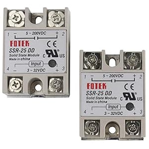
9. TIHOOD 2PCS SSR-25 Solid State Relay DD DC-DC 25A 3-32VDC/5-200V DC SSR-25DD
Solid State Relay,Model: SSR-25 DDInput voltage: 3-32VDC, Output voltage: 5-200VDCOutput current: 25A

Specs:
| Color | Grey |
10. Functional Devices RIBU1C Enclosed Pilot Relay, 10 Amp Spdt with 10-30 Vac/Dc/120 Vac Coil
- Relay In A Box (RIB)
- Coil Current: 28 mA @ 120 Vac ;
- HP @ 120V 1/3 NO, 1/6 NC, HP @ 240V 1/3 NO, 1/6 NC
- Enclosed Pre-Iwre Relay
- Coil Voltage Input: 10-30 Vac/dc ; 120 Vac ; 50-60 Hz ; Drop Out = 2.1 Vac / 2.8 Vdc ; Pull In = 9 Vac / 10 Vdc
Features:

Specs:
| Color | Gray |
| Height | 1.8 Inches |
| Length | 2.8 Inches |
| Weight | 0.25 Pounds |
| Width | 1.8 Inches |
| Release date | November 2017 |
| Size | full size |
| Number of items | 1 |
11. Ogrmar SSR-25 DA 25A 3-32V DC / 24-380V AC Solid State Relay and Heat Sink
- 12 AC Outlets & 3 USB Ports: 6 widely spaced Outlets & 6 regular Outlets, plus 2 Smart USB Charging Ports with Smart IC Technology (5V/3.1A) and 1 usual USB Charging port makes it an all-in-one charging station to satisfy all your charging needs.
- Comprehensive Protection: 4000 Joule rating Surge Protection with built-in LED light safeguards your expensive computers, laser printers, smart phones, home theater systems and all other electronics from voltage fluctuations, surges and spikes. HOLSEM’s comprehensive protection has got you covered all around with surge protection, lightning protection, overload protection, short-circuit protection, and output temperature control. guaranteed quality of ETL and FCC.
- 6 Feet Heavy Duty UL listed Extension Cord: Extra thick UL listed power cord provides better conductivity, less heat, less energy loss, and more safety, ideal for home office and professional workstations.
- Flame Retardant Material: Withstands temperature up to 1,380℉(750℃) for extra safety. 4 Keyhole Mounting Slots on the back allows you to easily mount it to a wall horizontally.
- What you will get: one Surge Protector, one User Guide and one Warranty Card; Worry-free 24-month warranty, 30-day no-hassle return & refund guarantee and life time technical support.
Features:
 ▼ Read Reddit mentions
12. uxcell A11063000ux0053 DPDT HH52P Coil 8 Pin General Purpose Relay with PYF08A Socket, DC 12V
Product Name : Relay with Socket;Relay Model No. : HH52P;Socket Model No. : PYF08ACoil Voltage : 12VDC;Contact Capacity : 5A, 240VAC;5A, 28VDC : 5A, 28VDCNumber of Pins : 8;Overall Size(Approx.) : 70.5 x 22 x 65mm/2.8" x 0.9" x 2.56"(L*W*H)Material(External) : Plastic;Color : Clear, BlackWeight : 61...

Specs:
| Color | Clear, Black |
| Height | 1.18 Inches |
| Length | 4.33 Inches |
| Weight | 0.134375 Pounds |
| Width | 3.94 Inches |
| Number of items | 1 |
13. (x2) PC537-1C-5S-X-2 | SPDT 5 VDC Coil 30/25 Amp 14 VDC Ultra Miniature Automotive PCB Relay
- 30 Amp 14 VDC Resistive Load Contact Rating, 100 Amp Make 40 Amp Break 14 VDC Rated
- -40 to +105C Operating Temperature
- 5 VDC / 577 mWatt Coil, -40 to105C Operation Temperature
- Cross Reference: TE V23086-C1001-A403
Features:

Specs:
| Weight | 0.00875 Pounds |
| Number of items | 2 |
14. HiLetgo 2pcs 5V One Channel Relay Module Relay Switch with OPTO Isolation High Low Level Trigger
- The module uses genuine quality relay, normally open interfaces , Maximum load: AC 250V/10A, DC 30V/10A.
- Using SMD optocoupler isolation, strong driving capability, stable performance; trigger current 5mA.
- Fault-tolerant design, even if the control line is broken, the relay will not move.
- The interface design of human nature, all interfaces are available through a direct connection terminal leads, very convenient.
- The Module can be set by jumper high or low trigger.
Features:

Specs:
| Color | Red |
| Size | Small |
15. Functional Devices RIB2401B Power Relay, 20 Amp SPDT, 24 Vac/dc/120 Vac Coil, NEMA 1 Housing
- Product Type:Dip Switch
- Item Package Weight:0.204 Kilograms
- Item Package Dimension:6.35 cm L X11.176 cm W X17.018 cm H
- Country Of Origin: United States
Features:

Specs:
| Color | Gray |
| Height | 6.6 Inches |
| Length | 4.4 Inches |
| Width | 2.5 Inches |
| Release date | November 2017 |
| Size | Original |
| Number of items | 1 |
16. SainSmart 5V 2A 8 Channel Solid State Relay Module High Level Trigger Black for Arduino Uno Duemilanove MEGA2560 MEGA1280 ARM DSP PIC

Specs:
| Weight | 0.000625 Pounds |
17. TinaWood 2PCS SSR-25DD Solid State Relay 25A 3-32V DC/5-200V DC (SSR-25DD x2) (DC to DC 25A x2)
Solid State Relay,Model: SSR-25 DDInput voltage: 3-32VDC, Output voltage: 5-200VDCOutput current: 25A
Specs:
| Color | DC to DC 25A x2 |
18. Frentaly Output 24V-380V 25A SSR-25 DA DC-DC Solidstate Solid State Relay for Arduino Raspberry Pi
Guarantee the quality of productsSame Day shipping. May receive as quickly as in 2 daysLong service life and high reliabilityDesigned to offer users maximum simplicityOutput Voltage: 24-380 VAC and Output Current: 25A

Specs:
| Height | 2 Inches |
| Length | 8 Inches |
| Width | 1 Inches |
19. 2ch Relay Shield Module
Product name : relay shield module; fit for : for ArduinoRated coil Voltage : dc 5V; rated Voltage & current : 10A 250Vac, 10A 125Vac,10A 30Vdc, 10A 28VdcTotal size : 5 x 4 x 2Cm/2" x 1.6 inch x 0.78"(L*w*h); materials : plastic, pcb, Fr4Net weight : 30GPackage Content : 1 x relay shield module

Specs:
| Height | 0.78 Inches |
| Length | 2 Inches |
| Width | 1.6 Inches |
| Number of items | 1 |
20. Omron G3NA-210B-DC5-24 Solid State Relay, Zero Cross Function, Yellow Indicator, Phototriac Coupler Isolation, 10 A Rated Load Current, 24 to 240 VAC Rated Load Voltage, 5 to 24 VDC Input Voltage
- Solid state relays for high-speed switching in low current applications
- Screw terminals for connecting to contacts
- Noise suppression activated when the load current rises suddenly
- Yellow operation indicator alerts users to operating status
- UL listed for safety, CSA certified for quality assurance, and RoHS compliant for hazardous substances
Features:

Specs:
| Height | 3 Inches |
| Length | 3 Inches |
| Weight | 0.05 Pounds |
| Width | 3 Inches |
| Size | Phototriac Coupler Isolation |
| Number of items | 1 |
🎓 Reddit experts on electrical relays
The comments and opinions expressed on this page are written exclusively by redditors. To provide you with the most relevant data, we sourced opinions from the most knowledgeable Reddit users based the total number of upvotes and downvotes received across comments on subreddits where electrical relays are discussed. For your reference and for the sake of transparency, here are the specialists whose opinions mattered the most in our ranking.
Subcategories:
Interested in what Redditors like? Check out our Shuffle feature
Shuffle: random products popular on RedditTop Reddit comments about Electrical Relays:
Summary
1. SainSmart 4-Channel Relay Module
- 5V 4-Channel Relay interface board, and each one needs 15-20mA Driver Current
- Equipped with high-current relay, AC250V 10A ; DC30V 10A
- Standard interface that can be controlled directly by microcontroller (Arduino , 8051, AVR, PIC, DSP, ARM, ARM, MSP431, TTL logic)
- Indication LED's for Relay output status
Features:
Specs:
| Height | 1.19 Inches |
| Length | 4.5 Inches |
| Weight | 0.000625 Pounds |
| Width | 3.2 Inches |
| Size | 4-Channel |
| Number of items | 1 |
2. SainSmart 2-Channel Relay Module
5V 2-Channel Relay interface board, and each one needs 15-20mA Driver CurrentEquipped with high-current relay, AC250V 10A ; DC30V 10AStandard interface that can be controlled directly by microcontroller (Arduino , 8051, AVR, PIC, DSP, ARM, ARM, MSP430, TTL logic)Indication LED's for Relay output sta...
Specs:
| Height | 0.1 Inches |
| Length | 4.79 Inches |
| Weight | 0.1 Pounds |
| Width | 0.69 Inches |
| Release date | December 2012 |
| Size | 2-Channel |
| Number of items | 1 |
3. ELEGOO 8 Channel DC 5V Relay Module with Optocoupler for Arduino UNO R3 MEGA 2560 1280 DSP ARM PIC AVR STM32 Raspberry Pi
5V 8-Channel Relay interface board, each one needs 70mA Driver Current; Equiped with high-current relay, AC250V 10A ; DC30V 10AEach relay has normally open and normally closed contact. Can be selected by jumper relay and TTL or ground.With power indicator,8-way road has a status indicator. With a re...
▼ Read Reddit mentions4. SainSmart 16-Channel Relay Module
- 12V 16-Channel Relay interface board, and each one needs 15-20mA Driver Current
- Equipped with high-current relay, AC250V 10A ; DC30V 12A
- Standard interface that can be controlled directly by microcontroller (Arduino , 8051, AVR, PIC, DSP, ARM, ARM, MSP433, TTL logic)
- Indication LED's for Relay output status
Features:
Specs:
| Height | 1.19 Inches |
| Length | 8 Inches |
| Weight | 0.55 Pounds |
| Width | 5.7 Inches |
| Release date | May 2018 |
| Size | 16-Channel |
| Number of items | 1 |
5. uxcell Solid State Relay + Heat Sink SSR-25 DA 25A 3-32V DC / 24-380V AC
- Relay In A Box (RIB)
- Coil Current: 28 mA @ 120 Vac ;
- HP @ 120V 1/3 NO, 1/6 NC, HP @ 240V 1/3 NO, 1/6 NC
- Enclosed Pre-Iwre Relay
- Coil Voltage Input: 10-30 Vac/dc ; 120 Vac ; 50-60 Hz ; Drop Out = 2.1 Vac / 2.8 Vdc ; Pull In = 9 Vac / 10 Vdc
Features:
▼ Read Reddit mentions6. ELEGOO 4 Channel DC 5V Relay Module with Optocoupler for Arduino UNO R3 MEGA 2560 1280 DSP ARM PIC AVR STM32 Raspberry Pi
This relay module is 5V active low. Relay output maximum contact is AC250V 10A and DC30V 10A.Standard interface can be directly connected with microcontrollers.Working status indicator lights are conducive to the safe use4-channel relay interface board, which can be controlled directly by a wide ran...
▼ Read Reddit mentions7. Icstation 3V 1 Channel Relay Power Switch Module with Optocoupler Opto Isolation High Level Trigger for IOT ESP8266 Development Board (Pack of 5)
- 【Optocoupler Isolator】 3V/3.3V power relay module supports photocoupler isolation control.
- 【High Level Trigger】The relay module is triggered by high level signal, which can be input from microcontroller IO.
- 【Jumper Caps】You are free to select whether the relay and the signal share the same power supply or not by removing the jumper caps on the pins or not. It is recommended to share the same power supply, because that is more convenient for using.
- 【Rotate Screw Terminals】 The external connection adopts a rotary crimping terminal, which makes the crimping more firm, and has fixed mounting holes for easy installation.
- 【30VDC 250VAC Load】The power switch is compatible with 10A 250VAC and 10A 30VDC load.
Features:
Specs:
| Color | Blue |
| Height | 0.79 Inches |
| Length | 2.76 Inches |
| Weight | 0.04 Pounds |
| Width | 0.7 Inches |
| Size | 5pcs |
| Number of items | 5 |
8. GLE2016 Single Phase Solid State Relay DC-DC SSR-40DD 40A DC3-32V DC5-60V
- Shade Description - Rosy nude
- A full-pigment liquid formula that dries down to a weightless matte finish for smudge-proof wearability and long-lasting color.
- Features a double-sided flat applicator with a rounded tip that distributes the perfect amount of product for precise application
- The long-wearing shades are versatile enough for customization, so you can mix and match multiple shades without losing pigment
- Available in 45 shades
Features:
▼ Read Reddit mentions9. TIHOOD 2PCS SSR-25 Solid State Relay DD DC-DC 25A 3-32VDC/5-200V DC SSR-25DD
Solid State Relay,Model: SSR-25 DDInput voltage: 3-32VDC, Output voltage: 5-200VDCOutput current: 25A
Specs:
| Color | Grey |
10. Functional Devices RIBU1C Enclosed Pilot Relay, 10 Amp Spdt with 10-30 Vac/Dc/120 Vac Coil
- Relay In A Box (RIB)
- Coil Current: 28 mA @ 120 Vac ;
- HP @ 120V 1/3 NO, 1/6 NC, HP @ 240V 1/3 NO, 1/6 NC
- Enclosed Pre-Iwre Relay
- Coil Voltage Input: 10-30 Vac/dc ; 120 Vac ; 50-60 Hz ; Drop Out = 2.1 Vac / 2.8 Vdc ; Pull In = 9 Vac / 10 Vdc
Features:
Specs:
| Color | Gray |
| Height | 1.8 Inches |
| Length | 2.8 Inches |
| Weight | 0.25 Pounds |
| Width | 1.8 Inches |
| Release date | November 2017 |
| Size | full size |
| Number of items | 1 |
11. Ogrmar SSR-25 DA 25A 3-32V DC / 24-380V AC Solid State Relay and Heat Sink
- 12 AC Outlets & 3 USB Ports: 6 widely spaced Outlets & 6 regular Outlets, plus 2 Smart USB Charging Ports with Smart IC Technology (5V/3.1A) and 1 usual USB Charging port makes it an all-in-one charging station to satisfy all your charging needs.
- Comprehensive Protection: 4000 Joule rating Surge Protection with built-in LED light safeguards your expensive computers, laser printers, smart phones, home theater systems and all other electronics from voltage fluctuations, surges and spikes. HOLSEM’s comprehensive protection has got you covered all around with surge protection, lightning protection, overload protection, short-circuit protection, and output temperature control. guaranteed quality of ETL and FCC.
- 6 Feet Heavy Duty UL listed Extension Cord: Extra thick UL listed power cord provides better conductivity, less heat, less energy loss, and more safety, ideal for home office and professional workstations.
- Flame Retardant Material: Withstands temperature up to 1,380℉(750℃) for extra safety. 4 Keyhole Mounting Slots on the back allows you to easily mount it to a wall horizontally.
- What you will get: one Surge Protector, one User Guide and one Warranty Card; Worry-free 24-month warranty, 30-day no-hassle return & refund guarantee and life time technical support.
Features:
▼ Read Reddit mentions12. uxcell A11063000ux0053 DPDT HH52P Coil 8 Pin General Purpose Relay with PYF08A Socket, DC 12V
Product Name : Relay with Socket;Relay Model No. : HH52P;Socket Model No. : PYF08ACoil Voltage : 12VDC;Contact Capacity : 5A, 240VAC;5A, 28VDC : 5A, 28VDCNumber of Pins : 8;Overall Size(Approx.) : 70.5 x 22 x 65mm/2.8" x 0.9" x 2.56"(L*W*H)Material(External) : Plastic;Color : Clear, BlackWeight : 61...
Specs:
| Color | Clear, Black |
| Height | 1.18 Inches |
| Length | 4.33 Inches |
| Weight | 0.134375 Pounds |
| Width | 3.94 Inches |
| Number of items | 1 |
13. (x2) PC537-1C-5S-X-2 | SPDT 5 VDC Coil 30/25 Amp 14 VDC Ultra Miniature Automotive PCB Relay
- 30 Amp 14 VDC Resistive Load Contact Rating, 100 Amp Make 40 Amp Break 14 VDC Rated
- -40 to +105C Operating Temperature
- 5 VDC / 577 mWatt Coil, -40 to105C Operation Temperature
- Cross Reference: TE V23086-C1001-A403
Features:
Specs:
| Weight | 0.00875 Pounds |
| Number of items | 2 |
14. HiLetgo 2pcs 5V One Channel Relay Module Relay Switch with OPTO Isolation High Low Level Trigger
- The module uses genuine quality relay, normally open interfaces , Maximum load: AC 250V/10A, DC 30V/10A.
- Using SMD optocoupler isolation, strong driving capability, stable performance; trigger current 5mA.
- Fault-tolerant design, even if the control line is broken, the relay will not move.
- The interface design of human nature, all interfaces are available through a direct connection terminal leads, very convenient.
- The Module can be set by jumper high or low trigger.
Features:
Specs:
| Color | Red |
| Size | Small |
15. Functional Devices RIB2401B Power Relay, 20 Amp SPDT, 24 Vac/dc/120 Vac Coil, NEMA 1 Housing
- Product Type:Dip Switch
- Item Package Weight:0.204 Kilograms
- Item Package Dimension:6.35 cm L X11.176 cm W X17.018 cm H
- Country Of Origin: United States
Features:
Specs:
| Color | Gray |
| Height | 6.6 Inches |
| Length | 4.4 Inches |
| Width | 2.5 Inches |
| Release date | November 2017 |
| Size | Original |
| Number of items | 1 |
16. SainSmart 5V 2A 8 Channel Solid State Relay Module High Level Trigger Black for Arduino Uno Duemilanove MEGA2560 MEGA1280 ARM DSP PIC
Specs:
| Weight | 0.000625 Pounds |
17. TinaWood 2PCS SSR-25DD Solid State Relay 25A 3-32V DC/5-200V DC (SSR-25DD x2) (DC to DC 25A x2)
Solid State Relay,Model: SSR-25 DDInput voltage: 3-32VDC, Output voltage: 5-200VDCOutput current: 25A
Specs:
| Color | DC to DC 25A x2 |
18. Frentaly Output 24V-380V 25A SSR-25 DA DC-DC Solidstate Solid State Relay for Arduino Raspberry Pi
Guarantee the quality of productsSame Day shipping. May receive as quickly as in 2 daysLong service life and high reliabilityDesigned to offer users maximum simplicityOutput Voltage: 24-380 VAC and Output Current: 25A
Specs:
| Height | 2 Inches |
| Length | 8 Inches |
| Width | 1 Inches |
19. 2ch Relay Shield Module
Product name : relay shield module; fit for : for ArduinoRated coil Voltage : dc 5V; rated Voltage & current : 10A 250Vac, 10A 125Vac,10A 30Vdc, 10A 28VdcTotal size : 5 x 4 x 2Cm/2" x 1.6 inch x 0.78"(L*w*h); materials : plastic, pcb, Fr4Net weight : 30GPackage Content : 1 x relay shield module
Specs:
| Height | 0.78 Inches |
| Length | 2 Inches |
| Width | 1.6 Inches |
| Number of items | 1 |
20. Omron G3NA-210B-DC5-24 Solid State Relay, Zero Cross Function, Yellow Indicator, Phototriac Coupler Isolation, 10 A Rated Load Current, 24 to 240 VAC Rated Load Voltage, 5 to 24 VDC Input Voltage
- Solid state relays for high-speed switching in low current applications
- Screw terminals for connecting to contacts
- Noise suppression activated when the load current rises suddenly
- Yellow operation indicator alerts users to operating status
- UL listed for safety, CSA certified for quality assurance, and RoHS compliant for hazardous substances
Features:
Specs:
| Height | 3 Inches |
| Length | 3 Inches |
| Weight | 0.05 Pounds |
| Width | 3 Inches |
| Size | Phototriac Coupler Isolation |
| Number of items | 1 |
For a display I am using this: i2c 7-segment display, and if you are grabbing the display you can't use the Spark Core relay board because they use the lines that are setup for i2c to control relays instead.
So the total bill of materials for my build is:
I don't believe you can get a local spark cloud server going, but the beauty of it is that you don't have to. You can just use their cloud service for free and be able to read variables and run registered functions securely and remotely without any issues. How I have it set is so that the spark core by default won't control the temp but can be given a command to set the temp and then it will just hold that temp until a new command comes in. So far it has been holding my fermenter to within a degree and switching between temps nice and quickly. I am very pleased, but still want the BrewBlogger integration so I can setup what temp I want at what time and to record and graph the temps. By next week I should be pushing some code up to github, so I'll PM you then and give you a link.
You could easily run BrewBlogger off of a Pi if you didn't have another place to run it, but it's just a PHP website that would need a scheduled task to run to fetch temps.
Thanks for the detailed write-up on your safety mods!!
I've seen Solid State relays recommended over/instead of the MOSFETs you linked to. e.g. something like this but rated at 25A.
However I'm having trouble deciding which one on Amazon is compatible. Would I need one that is DC to AC or DC to DC?
Like would this one be appropriate? Or this one?
I'm looking at Amazon only because they ship from the US and I'm hoping to have a Mosfet or SSR in hand by next week.
EDIT: Doing some more research, it seems like one of these is what I need? Amazon results for SSR-40DD The recommended brands are Fotek, Auber and Crydom.
I did a similar project a couple years ago, but using a Raspberry Pi Zero W and a relay board. I used this relay board: https://www.amazon.com/gp/product/B01HEQF5HU/ref=ppx_yo_dt_b_search_asin_title?ie=UTF8&psc=1
It was quite happy controlling 24VAC.
I know you said you want an "all-in-one" board, but the ESP8266 is so small, it would be easy to connect it to the relay board and secure them together. That's what I did with the RPi0W - I just electrical taped it to the relay board. It ran quite happily for year before we moved house.
not after a quick search ( ,_,)
seems like all of the "smart home" products are 15amps
off the top of my head, you could accomplish the same goal using a relay board and some RIBs
https://www.amazon.com/dp/B071KFX63R/
https://www.amazon.com/dp/B000LEUJU6/
but you're venturing towards a rabbit hole of how complicated/expensive do you want this to be :)
maybe someone else knows of a 20amp smart switch, for an elegant solution.
Not quite what you want as it requires a lot of assembly, but I'm doing something similar using Hikvision cameras, z-wave, and OpenHAB on an old PC. This gets pretty powerful if you go all-in with automation.
I get a push notification to my phone, and also it grabs a frame from my hikvision camera and emails it to the SMS gateway for my mobile phone. I keep push notification because it's much faster to deliver.
I added a relay to my doorbell to use as a simple contact. I'm connected to a mimolite to connect into my automation. It's just wired in parallel with the existing chime like a second chime.
Functional Devices Ribu1C - Rib Relay, Enclosed 10 Amp Spdt https://www.amazon.com/dp/B000LESCI2/
My wife works overnights, so I'm also using the mimolite to silence the upstairs chime while my wife is sleeping by switching it to ring the basement chime. I can still hear it on the main level but not on the second. If the front door is not opened within 60 seconds, the house speaks a reminder alert. If doorbell is set to chime in the basement, it reduces volume to 60% for the reminder.
Here's my setup for reference. https://m.imgur.com/a/fzUE3
Bonus, I'm using a node.js service to watch alarm events from my hikvision cameras and relay those events into OpenHAB. This allows me to get notifications on in-camera crossline detection to alert me if someone is on the porch but hasn't rung the doorbell. http://www.ragingcomputer.com/2016/06/hikvision-motion-detection-in-openhab-using-node-js
Hi everyone! If you liked the electronics enclosure you can download the design files here -
1 | 7I76-5I25 PLUG-N-GO KIT | http://store.mesanet.com/index.php?route=product/product&product_id=215
1 | DROK LM2596 Analog Control Step-down Regulator Module | www.amazon.com/gp/product/B019RKVMKU
1 | DC Fan (120mm x 120mm x 25mm 24V) | www.amazon.com/gp/product/B01FBPQMXW
1 | Mesh Dust Filter for 120mm Fan | www.amazon.com/gp/product/B01M0A2UH0
3 | DIN Rail | www.amazon.com/gp/product/B015E4EIOK
1 | IEC320 Inlet Power Socket | www.amazon.com/gp/product/B00ME5YAPK/
4 | KL-5056 Stepper Motor Driver - 32 bit DSP Based | www.amazon.com/gp/product/B00O6DC8PW
1 | Emergency Stop Button Switch | www.amazon.com/gp/product/B0094GM004
25ft | 4 Pin Cable | www.ebay.com/itm/20M-4-Pin-5050-3528-RGB-LED-Strip-Light-Wire-Extension-Connector-Cable-Cord-Line-/282110056592?hash=item41af11d890
1 | Antek Linear Power Supply - 500W 30V 16A Peak 25A With Passive Filters / EMI-RFI Filters and Suppressors | https://www.ebay.com/itm/PS-5N30-500W-30V-16A-Peak-25A-Stepper-Motor-Antek-Linear-Power-Supply-/371664502398?hash=item5688ee3e7e
3 | Wall Outlets from Home Depot | Find ones you like / feel are safe enough using
16ft | Led Strip Lights | www.amazon.com/gp/product/B01GJ3O0J8/
1 | Misc. Hardware | Nuts, Bolts, Standoffs, Crimp Connectors, Spare Fuses, 2 Extra Limit Switches
2 | Ogrmar SSR-25 DA Solid State Relay with Heat Sink | www.amazon.com/gp/product/B074FT4VXB/
1 | 18 AWG Gauge Stranded Hook-Up Wire Kit | www.amazon.com/gp/product/B00N51OO7Q
~30pc | Heat Shrink Tubing | www.amazon.com/gp/product/B00OZSL8UE
1 | Shop-Vac | www.amazon.com/gp/product/B00EPH63K0
7 | Uxcel 16mm Thread 4-Pin Panel Mount Wire Connector | www.amazon.com/gp/product/B016FCZ5SS
2 | 8 Circuit 20A Terminal Block | www.amazon.com/gp/product/B000S5Q2VS
Best of luck! Feel free to PM me or comment with any questions or feedback!
Exactly, yes! Everything that requires precise timings, instant response, and/or 5 volt logic would be on the Arduino and the Pi would just handle user interactions.
You could just get an Arduino Uno 3, that's kind of the standard Arduino board especially for people just learning. I just prefer the Mega because it is beefier and has way more GPIO pins. But the Uno 3 has enough to run three relays and your IR sensor easily (which has both 3.3 V and 5 V logic, meaning it can work with the Pi and Arduino respectively).
Speaking of relays, I really like the SainSmart ones and have never had an issue with them. This four-relay module is only $10:
https://www.amazon.com/SainSmart-101-70-101-4-Channel-Relay-Module/dp/B0057OC5O8/ref=asc_df_B0057OC5O8/
Only thing is, and you might know this already, these things are pull-down rather than up. Meaning instead of pushing a 5V signal straight from a digital GPIO pin on the Arduino straight to the relay, you have to use a transistor to basically invert the signal. When the Arduino activates the transistor, it allows the pin on the relay board to go to ground which turns it on. Also, don't forget to always wire so the power off side is your closed side for all valves and such! The last thing you want if a board dies is to have the relay that controls your solenoid valve to default to power on, dumping all your liquid!
It definitely is overwhelming at first, but once you get really confident it opens up a whole new world of fun engineering!
I ended up building a relay-controlled outlet that I plug an aqualifter in to, and put it all in a project box. The parts including a 5-pack of float switches cost me around 20 bucks total (mostly on amazon). I used this relay (https://www.amazon.com/gp/product/B00843IV06), a flyback diode I had on hand, this project box (https://www.amazon.com/gp/product/B0002BENLY), a pair of generic float switches, an outlet adapter (https://www.amazon.com/gp/product/B00GN61W48) and a couple parts I had on-hand (generic power cord [just cut the end off], and 12v power supply [I broke the brick and fit the parts in the project box, then split the AC in to power both the 12v transformer and passthrough the relay to power the outlet).
I used two float switches at two different heights. The bottom is for the actual water level, and I set the top one just below the baffle height in the return section of my sump - if it ever lifts, it cuts power to the pump.
I also have this plugged in to a digital timer with 8 adjustable timer periods as a failsafe. I measured my evaporation in one day and found I lost roughly 1 gallon in 24 hours. I allow the ATO to run for 5 minutes at each of 3/6/9/12 am/pm for a total of 40 minutes per day possible, which is roughly 2 gallons per day maximum.
Google is your friend for wiring the relay. No soldering required since I bought the relay with a socket. Fitting everything in the project box was a little tight, but it worked out. I mounted it to the side of my sump with 3m-backed zip tie mounts (like this - https://www.amazon.com/3M-Cable-2-way-Adhesive-CTB1X1BGA-C/dp/B00745TPY6) - the wires on the float switches were not long enough to have it further from the tank.
Good luck! It was a fun project and should hold me over until I can convince myself to buy a tunze osmolator (maybe next year).
Edit - overall, the project cost me about 35 bucks, plus the cost of a pump, since I had some parts on-hand already.
You can! The best way to do this is to use the ESP8266's GPIO pins to send a PWM signal to your 240v device through a solid state relay. ( https://www.amazon.com/TIHOOD-SSR-25-3-32VDC-5-200V-SSR-25DD/dp/B07PQL4CM6 )
This allows you to use the ESP's 3/5v signal to safely control the 240v device. It's fairly easy too! Hit me up if you want some more pointers :)
Alright, ya know what, fine. I'm going with this https://www.amazon.com/PC537-1C-5S-X-2-Ultra-Miniature-Automotive-Relay/dp/B07FP593R4 being controlled by my regulator PCB at 6 volts (on the coil side) and using active braking at the full 7.4 volts for the switch side, throwing a 1N4500 diode between the motor and relay cause I don't know if back EMF can f*** up the relay, and I'm gunna do the same between the relay and the PCB just to be careful because I don't fully understand if I should be worried about that. Happy?
​
Edit: for the sake of those reading-up on this subject later, I installed the relay linked above last night and everything is working well so far! The feed-rate of my magazines is now the limiting factor, though when they do feed correctly, I have indeed seen a noticeable increase in darts-per-second now that the Meishel 2.0 motors are getting all the voltage and current they desire. However, because of the inconsistent feed rate, I can't really estimate how many darts per second I'm averaging after the upgrade.
I'm not really pro-grade in this kind of stuff, however, if I were to go after something like this, an Arduino seems almost perfect. For anything you need to control, I'd use this type of relay designed to plug straight into Arduino IO pins and as far as the inputs, you could probably use relays wired up to a simple 5v source so you isolate the power within the pinball machine from clean 5v power for your Arduino.
As far as the display, instead of an LCD, I would probably chase some larger 8-segment displays, easier to see and much easier to control. One option would be to run 2 Arduino systems with one dedicated to the scoreboard and one dedicated to the automation.
ok, ramble off, but this sounds like a project I'd like to take on now...
> Would it matter which side of the motor circuit I place the relay in?
No
>Do I require any of the auxiliary electronic components like the flyback diode and/or some resistors if I go the route of using a relay?
Putting a flyback diode and some suppression caps near the motor might be a good idea to reduce noise/EMI since electronics are present, but the relay contacts don't need either any more than a direct-acting switch does. The coil which is being driven by the solid-state power stage should have a flyback diode.
>Since I'm running 2 fangs for the motors, but only a M2.0 for the pusher, and both connect to ground separately, that means I only need to find a relay that can hold up to the stall amperage of JUST the M2.0, not all 3 combined, right?
Yes
>or perhaps this: https://www.amazon.com/PC537-1C-5S-X-2-Ultra-Miniature-Automotive-Relay/dp/B07FP593R4 ?)
That would work:
The relay setup and wiring is not hard but it can be a bit confusing at first until you figure out the GPIO wiring and setup. With my setup I can control a power strip that the Pi (via Octoprint menu entry) can turn on or off via the relay as well as having LED lighting inside my enclosure controlled that can also be controlled from Octoprint. If you want to give it a go just pick up a relay and some connectors to wire it to the GPIO pins. Feel free to hit me up once you have the hardware and I can share my wiring and Pi GPIO config with you so you can get going quickly. I like the 4 channel relays since they are only a few bucks more than the 1 or 2 chan versions and it allows you to add devices in the future. They are under $10: https://www.amazon.com/gp/product/B0057OC5O8/ref=oh_aui_search_detailpage?ie=UTF8&psc=1
Thanks for the safety advice, that's obviously something I want to be careful with. I'm looking at getting this keenovo 200x300mm heater and this SSR. What kind of fuses do you recommend for something like this?
Wow Thanks for the descriptive response!
I'm not very great at electronics, but here is the exact switch I'm using.
As for power source, I'm probably going to use 110 VAC to power the 4 ch relay board. http://www.amazon.com/SainSmart-101-70-101-4-Channel-Relay-Module/dp/B0057OC5O8
This is the solenoid I will be using
Thanks! Your post really helped me think it through. Just need to put it to work lol.
Earlier this week I realized my brew calendar had a few glaring issues. All fixed now, but it does mean I am brewing this weekend (mash tonight, boil Saturday morning) instead of the next. Hopefully the (long) boil and following steps will go without issues as I'm on call for most of the day, only needing to intervene if something goes wrong with the project.
Edit: I need to buy a relay shield. Picked up a thermoelectric travel cooler/warmer someone threw out (with manual and AC/DC transformer); it rained earlier that evening so I cleaned it up and let it dry overnight, testing it the next day: worked well enough, brought the few bottles I threw in down to ~32F below ambient though I haven't tested the warmer part yet. Still, if the latter works I would now have a way to brew Saisons during winter. I have plenty of Arduinos lying around and a relay shield, unfortunately that cooler draws 12VDC/6A, way more than my relay shield can handle. Looks like this one should do the trick. Temp sensor will be a TMP36 since I already have a few. I'd yank the thermoelectric part from this cooler, build a styrofoam box large enough for the biggest fermentor I have (3 gallon carboy) and hope for the best - my expectations are that it will be able to handle a 65F-80F range well enough in summer and winter (we don't run the AC when we're out, so the house sometimes gets warmer than 85F in the summer; winter, it's about 70F-74F).
I would replace your discrete components with an Arduino Pro Mini. You can connect three output pins to some relays, and drive the LEDs with a 5V power supply. You'll probably want to put a resistor in series with each LED, instead of one resistor for the whole string, to minimize risk of damaging them: (5V-3.4V)/.025A = 64Ohms, so use somewhere between 50 and 75 Ohms for each LED. Alternatively, you could run the whole thing on 3.3V and skip the resistors, but those power supplies aren't so common. In that case you'd want the 3.3V Arduino. PM me if you need help programming the Arduino, it's pretty easy.
If you want a hot fix, set pinmode to input instead of switching to high. Make sure there's no sort of pullup on the pin. I had good luck with the spi pins.
By setting it to input, the pin will hopefully go into a floating or hi-z state. If all is well, the relay will open when switched to input and close when switch to HIGH output.
Worked for me until I found some single 3v relays. You could also use transistors to convert signal to 5v.
I'm currently struggling with the same problem with my project.
You'd probably want to put a DHT11 in each pot attached to GPIO on the Pi.
The soil RH (relative humidity) could be used to determine whether to power a 12v pump or solenoid valve (if gravity fed).
Relays are super easy to set up and control using a Pi and relatively safe at 12v. The difficult question here is how to direct the water into whichever pot requires what amount of water. A naive approach is one pump per pot but that could get costly... hmm
I'm using this pump
I'm using this relay
Here's the code to read digital Celcius and RH from the DHT
I'm also considering adding an additional 'misting' nozzle to help control my super-hot (not ideal) environment :
Soil > Tempenature : 37.0 Humidity : 77.0
Feel free to follow up in PM if you have any questions.
[Here's a relay] ( http://www.amazon.com/gp/aw/d/B0057OC5O8?qid=1427254414&sr=8-6&vs=1#)
Wiring is pretty intuitive.
12v DC > Relay 1 blue connector 1
Motor positive wire > Relay 1 blue connector 2.
Connect Arduino ground and digital IO (set to output) pins to the pins associated with the relay that you chose, raise the DIO pin to High, and the relay will connect the motor to the power supply.
Technical note: These relays trip at 15-20ma, so there shouldn't be any issues using a DIO pin. If you choose a different relay, MAKE SURE the relay input draws less than 40ma, otherwise you may damage your Arduino. This relay board is also protected by diodes, so your Arduino is shielded completely from the 12v.
There's not much to it, depending on the relay you have.
Relay's have two parts, a coil and one or more sets of contacts. The coil is what controls the contacts. The coil is an electromagnet, and the contacts are reed switches. When the coil is energized, it causes the reed switches to engage. So by using the contacts as part of a circuit, you can make or break the circuit by engaging the relay.
Relay coils by themselves pull too much current to safely run one with a raspberry pi, so you'll most likely need a transistor to control the relay (a transistor can act more or less like a tiny relay with no moving parts).
If you've bought a pre-packaged relay board (such as one like this) then they've taken care of the transistor for you and all you have to do is hook VCC to the pi's 5V pin, the ground to the pi's ground, and the input you want to control on the board to the output on the raspberry pi.
There are plenty of tutorials out there that show you how to use python to control the pins.
On these particular relays, there are three terminals for the contacts, NO (normally open), common, and NC (normally closed). To switch a circuit you connect one wire to common (usually the middle terminal) and the other wire to either NO or NC depending on if you want the circuit to be On (NC) or Off (NO) when the coil is de-energized. Don't connect a wire to NO and the other to NC and expect anything to happen, they're not connected together. One wire must go to Common for there to be a complete circuit. You are free to connect to all three and switch your common line between two different circuits (one for NO and one for NC)
Sure! You'll need a relay to handle the higher voltage from wall outlet, or from the wiring in the strand itself. I have a 4-channel version of this that works great: http://www.amazon.com/SainSmart-2-CH-2-Channel-Relay-Module/dp/B0057OC6D8
If you want a finished solution, Belkin makes WeMo devices you can control from an iPhone or Android, or setup trigger with IFTTT: http://www.amazon.com/Belkin-Automation-Switch-Apple-iPhone/dp/B0089WFPRO
I recommend going with a mains powered silicone heating pad, switched by a solid state relay, adhered to a cast aluminum tooling plate, with a PEI sheet adhered to the aluminum as a build surface. It costs a good amount more and is worth it. Of course you will need to play around with sizing things (you may want to go with a smaller heating pad for instance), selecting things for the voltage in your country (I linked 110V stuff), and whether or not you are comfortable working with mains voltage.
Honestly a board like this is way easier
4ch relay
See all the extra thing on there? Optos, transistors, resistors, and diodes. You need that in addition to the relay.
As far as a pi being enough to trigger, I’ve never tested. Someone else know?
Seems like it would be pretty simple - find a cheap/quiet air compressor, run the line through a normally-closed solenoid (found this for 11 bucks), and control the solenoid w/ the arduino. If the solenoid is higher than the 5V the arduino can supply, have the arduino power a relay or a power transistor, I use a 12 channel one of these to power solenoids for dispensing water and it works well. Sounds like y'all already have the code set up to do something similar, but give a shout if you need help with that part too
Probably the best way would be with a relay. They're electromagnetic operated switches and as a bonus the two circuits aren't connected so they can't interfere with each other. I bought a 4 relay version of this board and I can control it directly from an Arduino with only a couple of wires.
This.
I got one of these recently and it seems to work fine. Fairly cheap, super easy to use.
Take a look at using a contactor with a smaller relay to act as as a "bridge" to a MCU.
In other words (assuming you're working with two 120V "hot" legs and a neutral - verify this!):
https://imgur.com/fEHNtIr
You might want to use a 5V relay board to make it easier to wire.
Just make sure that you mount all the components in a safe enclosure (~$25 on Amazon).
Love the push/pull analogy. Thanks for that one, makes sense. Kind of a supply vs demand situation.
Yes, same power supply but only interact via a relay: GPIO2 on ESP-01 goes high (+3.3v, remember I'm still learning terminology here) when triggered via message, opens 3.3v relay (https://amzn.com/B01M0E6SQM) which connects 12v via step-up to gate remote which has it's button locked on. So 5v source split into 3.3v step down and 12v step up, separated by the relay downstream.
The setup allows me to skip two important features: needing to deconstruct/integrate with the remote board to replicate a button press (which would have been destructive) and needing to power off a battery (would have required ongoing replacement & cost).
In case anyone has this same problem, this opto-isolator board seems to have fixed the issue.
I was having issues with the limit switches triggering prematurely also, so I installed four of these boards (one per limit switch and one for the probe circuit) and installed an add-on board using this circuit and the probe and limit switches are now working perfectly. :)
Example
Don't. Use something like these.
I'm sure you could find them cheaper on Aliexpress or eBay, but I use these exact ones with NodeMCUs, WeMos D1 Minis, and WeMos D1 Mini Lites all the time. They work great.
Yes I would say the heated bed is a necessity if you want to print ABS the stock bed only reaches 45-50c and takes along time to heatup , the bed I bought is from folgertech it's the 12v silicone heated bed 300x300 and yes you could do a separate PSU as well I just didn't need to and the mosfet I bought is the trigorilla mosfet on Amazon, I would recommend that mosfet over any other as I bought a DCDC SSR and it didn't work, i then bought a BIQU mosfet on Amazon and it started smoking so I returned it but the trigorilla mosfet has had no issues so far, to add to my heated im going to add some cork to insulate it to hold the heat better.. hope this helps
Awesome dude. I was in the same spot as you. Ended up using some of these, but I have an LED fixture, so it's not drawing as much power at T5s. It works really great with the pi, and now I don't have to fuck with having 3 or 4 timers, and can change or control it all from my phone or computer without the pain in the ass of stooping under the tank.
Yeah, the arduino can supply only a couple mA from each IO pin, that pump likely needs 500-1000mA to run.
You can also use a relay for a more simple setup, like this board for example, it will let the arduino switch high current loads like the pump easily.
You can hook it up as they recommend for the 24v configuration but that just provides the same amount of power at a different voltage so that doesn't help.
If you hook up 24v to the 12v terminals, you will quadruple the power and double the current.
Ohm's law, 12V=(1.2ohm)(10A) or 24v=(1.2ohm)(20A)
You would probably need a 600W 24v power supply and all of your wiring needs to be 10awg at least.
Hook it up like this diagram shows, except your bed power will connect to the 24v psu instead of the 12v.
https://thingiverse-production-new.s3.amazonaws.com/assets/25/7d/4a/1d/63/D-Bot_Electrical_Diagram.pdf
Here's the relay used, be sure to heatsink it
http://www.amazon.com/Single-Phase-SSR-40DD-DC3-32V-DC5-60V/dp/B012SW6TB6/ref=sr_1_6?s=hi&ie=UTF8&qid=1444750548&sr=1-6&keywords=solid+state+relay+dc+-ac
Yeah, if you're not very experienced in electronics better stay with something already tested, specially for anything mains related!. Probably you could use one of these arduino relay boards, they're fairly cheap and are opto isolated to keep things safe.
Arduinos overlap quite a bit of PLC functionality. Instead of 24V, everything will be 3.3V or 5V. A PLC typically scans the ladder for inputs then executes everything "at the same time". In Arduino code, variables update immediately.
You'll probably want to look at Adafruit and Sparkfun for LCDs and buttons, as well as relay boards. Amazon carries some selection, but Adafruit and Sparkfun (for the most part) design and manufacture their own boards, so their support is a lot better. Note that if you use a lot of relays (>4), you'll need an external power supply to switch them all on at the same time since Arduinos can't provide enough current to drive tons of relay coils. The one I linked uses an external 12V supply, but I don't know if it's included.
Thanks again, would this be an acceptable relay to use.
https://www.amazon.com/HiLetgo-Channel-optocoupler-Support-Trigger/dp/B00LW15A4W/ref=pd_lpo_sbs_147_t_2?_encoding=UTF8&psc=1&refRID=G3S0E83TCCD6FZ78SFFW
or this one.
https://www.amazon.com/TinaWood-SSR-25DD-Solid-State-5-200V/dp/B07F3WGRP4/ref=sr_1_8?keywords=5+volt+dc+relay&qid=1566485708&s=gateway&sr=8-8
Yeah, something like this would be fine. Solid state relay board
Parts list is dependent on what controller you use. This is a decent one.
https://www.amazon.com/dp/B0195V53X8/ref=cm_sw_r_cp_awdb_t1_n5DWCbX7WY6NB
You will need a box or container for the pid and wires. A temp probe that will work in the 500c temps. And a solid state relay. https://www.amazon.com/uxcell-Solid-SSR-25-3-2-32V-24-380V/dp/B0087ZTN08/ref=pd_aw_fbt_328_3/147-7782181-2201822?_encoding=UTF8&pd_rd_i=B0087ZTN08&pd_rd_r=0b211574-6776-11e9-b475-c358acaaf9b4&pd_rd_w=As9SE&pd_rd_wg=uOeRp&pf_rd_p=3ecc74bd-d08f-44bd-96f3-d0c2b89f563a&pf_rd_r=X57XWHY664NJBVVBD0AS&psc=1&refRID=X57XWHY664NJBVVBD0AS&th=1
That's an example, I need to do more digging to make sure its capacity is ok. I think it should work.
In general, a pid controller says "turn on the relay when the temperature is between x and y. Turn off when the temperature reads z.
This type of probe would work
https://www.amazon.com/Perfect-Prime-TL1815-HeadProbe-Thermocouple-Temperature/dp/B0142S9J4S/ref=pd_aw_sbs_79_1/147-7782181-2201822?_encoding=UTF8&pd_rd_i=B0142S9J4S&pd_rd_r=49d6e55b-6777-11e9-af2b-df456cd2a423&pd_rd_w=eR1mx&pd_rd_wg=w1VKC&pf_rd_p=aae79475-6dc9-4a12-80e8-27b63108fa72&pf_rd_r=BHRC8SSGY71B2D18D2Q1&psc=1&refRID=BHRC8SSGY71B2D18D2Q1&th=1
Would something like this be good?
From what I can tell its rated 5v but can't find anything about running it at a different voltage. This is the relay I have Link. I just tested it with 12v instead and it works with that as well but at the moment it is working again on 5v as well and I can't tell if it will make a difference with the higher voltage.
The Raspberry Pi sets its own time with most out-of-the-box distros at boot up.
Controlling a power supply would actually be pretty easy with a relay.
I recommend the Sainsmart Solid State Relays. They are silent in function and if you cut apart an extension cord, you can put one pole through the relay and it's now programmable. Keep in mind that an 8 channel relay is probably overkill. There's also a 4 channel available on Amazon.
You can go with the MECHANICAL relay (as opposed to solid state) because they're cheaper and you can get a 1 channel relay, but they're VERY loud when they clack open or closed.
Not much to see yet. So far it is an R-pi, a few DHT11, a relay module, one (or maybe more) cheap PIR motion detectors, and a toggle switch.
I'm using Monkey webserver, and playing with some cgi scripting. I started piddling with HTML5, and I want to try to make it as nice as I can, but I am not a web developer, so I am having to slog through some of this. If it goes well, I might make a post in here or in /r/HomeAutomation
This is the relay I bought when I setup my doorbell sensor last month. It's worked great so far.
https://www.amazon.com/gp/aw/d/B000LESCI2/ref=ya_aw_od_pi?ie=UTF8&psc=1
What you are describing is using one heating system for stage 1 and second system as stage 2. You just need to connect an isolation relay for stage 2. Then configure it as 2 stage heating in ecobee and set the thresholds. An enclosed relay like this one is probably best. Functional Devices RIBU1C Enclosed Pilot Relay, 10 Amp Spdt with 10-30 Vac/Dc/120 Vac Coil https://www.amazon.com/dp/B000LESCI2/ref=cm_sw_r_cp_api_i_KRF2Db7WPP7H5
Thanks for the response. Here is the diode spec:
https://www.mouser.com/ProductDetail/GeneSiC-Semiconductor/MBR200100CT?qs=sGAEpiMZZMtQ8nqTKtFS%2FHVp1T5850G0TwaW7MIEjcA%3D
Sorry allow me to clarify the problem a bit more. The load I am driving is a motor controller attached to a 3 phase BLDC motor. On shutdown the motor causes the voltage to rise steadily to 60V and then back down to 36V. This causes the power supplies to trip their OVP circuits which require a power cycle to clear the fault. The motor controller and motor were originally meant to run of a 36V battery. The circuit diagram is as show here: https://en.wikipedia.org/wiki/Flyback_diode
The flyback diode seemed to work when I initially switched on the + 36 VDC line going to a motor controller and a motor. The power supplies were separated from the inductive load kick and this allowed me to reconnect after the energy had been dissipated. I believe the issue with the flyback diode after my initial success was due to this SSR:
https://www.mouser.com/ProductDetail/Crydom/HDC100D160?qs=sGAEpiMZZMtyXJl6MftlF9Ozj4Qj0dXsoS3PeWG6bs8%3D
Although I am unsure why this is the case. I am currently debugging it. The issue now seems that the SSR does not turn off quick enough or allows too much voltage through before closing tripping the OVP on the power supplies. In my initial setup, where the system worked as expected, I was using these SSR:
https://www.amazon.com/TinaWood-SSR-25DD-Solid-State-5-200V/dp/B07F3WGRP4/ref=sr_1_2?keywords=tinawood&qid=1552598915&s=industrial&sr=1-2
One used to trigger the motor controller low power signal and one to switch the 36 V power. The system at no load draws around 8 - 15 A so using the 40 A version worked out fine. However, during full operation, the system would draw around 60 - 80 A with some peaks of 100 A. I thought the Crydom SSR would work for the power line switch. The diodes were working when I checked them with a multimeter.
arclight: yeah, i'm liking the idea of the board though. But I ended up buying http://www.amazon.com/gp/product/B0057OC5O8/ref=oh_details_o02_s00_i00?ie=UTF8&psc=1
So one like this or this work? Whats the difference between the two?
Thank you so much. I was on and off the phone with ecobee earlier and they couldn't give me a straight answer.
I had already purchased this relay and have it ready to install.
https://www.amazon.com/gp/aw/d/B000LESCI2?psc=1&ref=yo_pop_mb_pd_title
I will give it a shot later this evening. Thanks again.
You dont. At least not directly without killing the board. That said there are ready to go relay boards you can order if you want a simple solution, or go read the other comment about using a transistor, he/she is dead on on how to do it.
That said, a transistor is kinda like a relay. Perhaps that's all you need if you are running a small device like a few LED's or something else small.
I was thinking this for relays, but wanted something smaller.
I plan on switching at least 14 turnouts, which would require two of the boards shown above.
Mosfets are definitely where I'm going now.
I considered that and opened up my piano to see how much effort that would take, but I found that because it's an upright and due to how the strings are positioned some of them are not at all easily accessible. :( On the bright side, I found these which will serve my purpose; now I just need to figure out how to control this from a raspberry pi. Thanks for the suggestion however!
The 120V part is the easiest and the most dangerous, so pay attention to it. A relay module like this acts like an SPDT switch ("changeover/three way switch") - or more like 4 of them. The light are wired up to the relays just like you'd wire up an ordinary room light to a switch.
The arduino just connects to the little pin header on the bottom and is completely isolated from the high voltage.
r/Arduino will be able to help you write the code (you'll only need the basics for this). IDK why the post was nuked, but you can make a new one asking about the optocoupler tapping of the speaker - it will require a bit of poking around to get an idea what sort of thing is going on in the speaker wires.
Those should work fine, but just for neatness is probably go for this 4 in 1 relay board https://www.amazon.com/dp/B01HEQF5HU/
First of all I'd connect just the relay board to the Arduino and check it still works with your sketch, you should hear it click on and off when the LEDs should work.
Then sort out wiring your strip.
> How did you have the relay connected to the GPIO?
Through this board, which seems to be properly (opto) isolated.
> how were you powering the whole setup?
USB of the Raspberry Pi to a wall wart.
> sounds like latch-up
If you still think it could be a latch-up (given the board I'm using), how would you recommend preventing it?
I have build a C-Bot and am currently using a Fotek 40A SSR you can get off of amazon. This was the listing recommended by the creator of the C-bot in his rework design btw. I have it attached to the aluminum extrusions directly with some heatsink compound between them and it barely gets warm during operation.
Managed to get nearly all of my printed components designed and printed on my ender 3 in PETG. Went with 0.2mm layer height and 7 shells. The corner brackets can take a hanging load of 200lbs with no deformation so I think it will be strong enough.
Think I'm going to have to go with a 310x310mm 110v bed heater. Anyone have experience controlling that with a 24v board? I'm thinking of using this.
Ogrmar SSR-25 DA 25A 3-32V DC / 24-380V AC Solid State Relay and Heat Sink https://www.amazon.com/dp/B074FT4VXB/ref=cm_sw_r_cp_apa_i_hz83DbVV5T3YP
Is there any reason I couldn't use a spare pc power supply to power the board and hot end? I have a 650w laying around from an old pc build.
The switch will be connected directly to the pi's GPIO, which will control a relay. The electrical wiring in the walls will be connected to that relay which is connected to the light. I'll be using a 2 channel relay, something similar to the link below. There are also 8 channel relays, so you can control 8 devices with only 1 Pi. I plan on using an 8 channel relay for a Pi controlled thermostat. Also, prices are much cheaper on eBay if you're willing to wait a few weeks for shipping.
http://www.amazon.com/SainSmart-2-CH-2-Channel-Relay-Module/dp/B0057OC6D8
But yes that would also work if you want to wirelessly control the relay, you just have to be connected to your WiFi.
The way I do it is with an Arduino and a 16-Channel Relay Module.
http://arduino.cc/
http://amzn.com/B0057OC66U
If you want the actual sound to play outside, you can do that with a sound board, speakers, and a cheap power supply.
http://www.adafruit.com/products/2217
Then you program the lights to trigger however you want.
Here's the relays I used. The reviews have some good documentation on current requirements and such. I ran 12V to the Vin of the relay boards, as well as to the common terminal of all 32 relays (since the goal was to supply 12V to an ematch when the cue was triggered). The positive end of the cue terminals were connected to the NO terminals of the relays. This means that normally, the ematches are disconnected. When a relay is triggered (by setting an Arduino pin to ground, thus triggering one of the active low relays on the board), the match on that relay is connected to the 12V source. Since the negative terminals on the channels are already grounded, boom.
E-match will detonate with around .5A of current, though most people recommend 1A per match to be sure. This is how we determine how many matches can be fired from one cue; we divide our 12V source by the resistance of all of our matches in series (typically around 2 ohms each) and ensure we can still supply 1A of current. Once the matches detonate, the circuit is broken. Does that clarify things?
Ok so looking into SSR's a little more I think I found one I can use. would this be what I want to use to turn on and off the 100W ceramic heating element and the fogger?
> something like this may be cheaper if you've got the equipment to properly crimp female spade terminals/quick connect terminals to your wire.
I do have a whole box of wire terminators and I do have those type so that would work.
>You want a relay with a nice excessive contact current rating, since DC motor loads are fairly harsh on relay contacts.
What kind of numbers should I be looking for then? The actuator draws up to 5A max. I did a search on Amazon (I try to order everything I need off there because I earn points!) and found this on but there are lots of options available:
https://www.amazon.com/Uxcell-General-Purpose-PYF08A-Socket/dp/B00843IV06/ref=sr_1_1?ie=UTF8&qid=1495645982&sr=8-1&keywords=DPDT+relay
Ok so the heat bed is here:
http://www.aliexpress.com/store/product/200X200mm-400W-12V-w-NTC-100K-Thermistor-Keenovo-Silicone-Heater-3D-Printer-Heater-Heatbed-First-Grade/210086_32230108542.html
and the relay is here:
http://www.amazon.com/Amico-Solid-State-SSR-25-24-380V/dp/B0087ZTN08/
(thanks to BillDaCat)
Where is the metal brace thingy? (or is that part of your printer? Or the fiberglass part?)
You need a heavy duty relay for your channels like the one below. Check out the Christmas lights forums. The guys with the crazy displays like Lindsay Lights have all this stuff figured out to a tee.
https://www.amazon.com/gp/aw/d/B017A1QUGO/ref=pd_aw_lpo_23_tr_img_2?ie=UTF8&psc=1&refRID=M4WFC6EYB1PMBX4DE59E
SSRs aren't hard to wire up and are a lot cheaper. I bought 20 of them on ebay for ~$20. If it's 12 V relays work well too. Amazon has a card that can control 16 relays for $40.
Yeah, I have ordered the resistors and breadboard, and will not repeat the 3v to 5v "solution" again.
But I'm curious where the failure is, exactly. Inside one of the components?
There's no documentation with the SainSmart 16 relay board, so I don't know if there are snubbers on the coils, but I'd be surprised if there were.
The opto-isolators are in place, so I wouldn't think the logic circuitry would be jeopardized by surges from deactivated coils.
https://www.amazon.com/dp/B00EDMIWRE/ref=cm_sw_r_sms_apa_9ca7xbF0JQ3DF
So to power a relay like this one here, you don't need an additional transistor right? I've always been confused on how to hook them up. Do I have to use a separate 5v power supply? Or can I power it through the arduino?
you can also find the omron ssr on amazon
https://www.amazon.com/gp/product/B003B316N8/ref=oh_aui_detailpage_o01_s00?ie=UTF8&psc=1
I didn't have a relay picked out yet, I'm kind of in the brain storming stage right now. I came across this board on amazon and thought it might do the trick:
https://www.amazon.ca/SainSmart-101-70-101-4-Channel-Relay-Module/dp/B0057OC5O8/ref=sr_1_21?ie=UTF8&qid=1486504628&sr=8-21&keywords=usb+relay
It says it has a Standard interface that can be controlled directly by microcontroller (Arduino , 8051, AVR, PIC, DSP, ARM, ARM, MSP431, TTL logic)
Maybe i'll give it a go.
your standard issue songle. https://smile.amazon.com/gp/product/B0057OC6D8
i took an old 5v straight wired micro usb cable and lopped off the usb end (the other end is part of the power supply not usb-a) and split the +5v into two legs, one powering the esp8266 (it's a nodemcu board) and the other leg providing power to the relays. ground is common to the entire system.
i haven't tested these (https://smile.amazon.com/gp/product/B07CQKMPDP) in the cold but one of them has been the heat "switch" for my esp8266 basement thermostat.
Rocking, thank you /u/DrkMith that's what I was hoping to hear. I have a 24vac isolation relay (https://www.amazon.com/dp/B000LEUJU6/ref=cm_sw_r_sms_apa_i_LyXQDbS071NWR) already hooked up to the stove.
Regards to the "C" wire, currently there is nothing hooked up to the nest C wire terminal. Looks like when I plug the Relay Coil wire into the "C" terminal, the Nest is throwing an error about no power to "Rc".
SSR or Solid State Relay. It's a switch to turn line voltage power on and off using low voltage (3-32VDC).
Here is one on Amazon with a heatsink.
I have been using an all-in-one Sainsmart Relay to control my garage door via the Pi.
This is the spare relay i have laying around. I believe it's DC to DC, right?
Currently it's an Arduino running an AD9851 module which is then connected to a pretty shameful homebrew amp. I also have it connected to a cheap relay board. One relay is used to switch power to the amp, the other switches the antenna feed between the amp output and the SDR chain (preamp, Ham It Up, RTL-SDR).
For software I've written some stuff to send RTTY and Morse.
SainSmart 2-Channel Relay Module https://www.amazon.com/dp/B0057OC6D8/ref=cm_sw_r_cp_apa_i_mgsFDbSR97ZA7
And the pi needs to have the pin initialized as an input / output pin. It must be getting a slight amount of current when just powed on but not initialized?
http://smile.amazon.com/SainSmart-4-CH-4-Channel-Relay-Module/dp/B0057OC5O8/
I ended up buying this relay module so I can actually switch both the lamp and the printer from the Pi.
Using your Arduino you can wire a relay and control it from your phone or computer
The board I bought is a 12v (since the solenoids are 12v), here's a link to it: SainSmart 16-Channel Relay Module https://www.amazon.com/dp/B0057OC66U/ref=cm_sw_r_awd_FCvSub144A8GM
I decided to do PWM. If I use a transistor I won't need a heat sink, right? Will I need any capacitors?
these are the parts I've found so far (Other than motion sensors, short jumper wires, and other common items)
Transistor \
Relays/ One or the other, transistors preferably
Wires
Nano Every
Breadboard(s)
Barrel Jack
Soldering Iron
Solder
Lights + Cable - Would the cable work with the barrel jack to provide power for the Nano Every and the LEDs?
Potentiometers
I can lend you 2 of these:
https://www.amazon.com/SainSmart-101-70-103-16-Channel-Relay-Module/dp/B0057OC66U/ref=sr_1_6?ie=UTF8&qid=1501860037&sr=8-6&keywords=sainsmart+relay
You can control any AC load within reason using a relay module. For example: http://www.amazon.com/SainSmart-2-Channel-Relay-Module-Arduino/dp/B0057OC6D8/
As for temperature control, you should look in to using PID.
Non-mobile: Here's a relay
^That's ^why ^I'm ^here, ^I ^don't ^judge ^you. ^PM ^/u/xl0 ^if ^I'm ^causing ^any ^trouble. ^WUT?
Right here: http://www.amazon.com/gp/product/B0057OC5O8/ref=oh_aui_detailpage_o00_s01?ie=UTF8&psc=1
This is the relay board I'm using. I'm going to use two separate arduinos to turn each one on (using "or" logic). I don't have a lot of experience using diodes, what exactly would I use? And do you mean literally I do:
Arduino1->Digital out->diode->Relay input1, then
Arduino2->Digital out->diode->Relay input1
Ya one minute I tried start_music_and_lights and they just turn on. I tried all 3 of the testing commands on the website and the lights turn on and nothing happens. I have pins 0-7 connected on my pi 2b and the 2 5v pins are connected to the relays 5v pins and 2 ground pins are connected to the 2 ground pis on my relay. The relay has an external power source of 12 volts
This is the relay I am using. https://www.amazon.com/gp/product/B0057OC66U/ref=ppx_yo_dt_b_asin_title_o00_s00?ie=UTF8&psc=1
I've got a relay from amazon connected to some of the GPIO pins, then a simple website I made on the pie that when I press a button on it, it flips the relay. The relay is wired to the door open button and does the same thing as me physically pressing the button in the garage. I also have it monitoring for an amazon dash button press that will also trigger the relay, that is by the front door so I can open the garage on my way out the door if I need.
​
However, this has all been running for 4+ years, I tried to review how I pieced it all together about a year ago and couldn't remember or figure out all the pieces, but it still continues to work, so I can't give much more detail than that sorry.
for a beginner, I would not recommend you do this. but if you will anyway, I suggest this: http://www.amazon.com/SainSmart-101-70-101-4-Channel-Relay-Module/dp/B0057OC5O8/ref=sr_1_4?ie=UTF8&qid=1462302659&sr=8-4&keywords=3.3v+relay
The hoist shares the ground and one of legs that powers the motor also powers the arduino. Ill try and sketch up a circuit quick. The relays I am using are [these] (https://www.amazon.com/gp/product/B0057OC66U/ref=oh_aui_search_detailpage?ie=UTF8&psc=1) which as far as I can tell have diodes and are optically isolated.
Hi Shadow, thanks for the response, the relay I'm using is this one from Amazon.
I connected the relay to the 5V power rail that's hooked up to the Arduino. The ground for the relay is connected to the ground of the Arduino. The signal wires are directly hooked up to the Arduino digital outputs (5,6,7). I have a photo of the circuit, but I must admit it's not the best picture.
http://i.imgur.com/tDr0nTw.jpg
Another thing I noticed, was that this occurred even when I disconnected the Arduino and just ran a 12V source through the component, it was worse when it was connected to the Arduino.
Not just from prusa, pick and choose. URLs for examples.
Digital caliper, 12" https://www.amazon.com/gp/product/B000EJUBBU/ref=oh_aui_detailpage_o02_s00?ie=UTF8&psc=1
Extra brass nozzles.
Hardened steel nozzle, 0.4mm to 0.6mm for printing abrasive exotics (wood, glow in the dark, carbon fiber etc)
Print removal tool https://www.amazon.com/gp/product/B00VB1U886/ref=oh_aui_detailpage_o02_s01?ie=UTF8&psc=1
Locktite blue bolt-fixer (Walmart, Home Depo, Lowes etc) to stop bed sensor from moving.
High temp anti-seize for nozzle threads https://www.amazon.com/gp/product/B0053ZS1Z8/ref=oh_aui_detailpage_o02_s01?ie=UTF8&psc=1
Raspberry Pi 3, 5v Pi 2A Power wart, Micro SD card, & Webcam for octoprint monitoring.
Relay board for Pi/octoprint to power up & down printer remotely. https://www.amazon.com/gp/product/B0057OC5O8/ref=oh_aui_detailpage_o04_s02?ie=UTF8&psc=1
1lb of silica gel to keep filament dry.
Filaments, various.
Fire extinguisher rated for electrical fires.
Dedicated smoke alarm.
I'm not clear what you mean by I/O board? If it's just the gpio header on the pi itself, it's 3.3v but at 10mA, maybe 12mA? Enough to drive a signal, but not enough to energize a coil. (If you do have a separate board, you'd have to either lookup the specs for it, or let us know which one so we can figure it out.)
So you'll need something to use that to push a relay. Typically a darlington pair, an optoisolator, or a trip to Amazon.
I'm cheap and lazy, so I regularly use either these, which are 3v modules, or these which are awesome, but do need 5v drivers (I usually use an MCP23018 between the pi & the relay board - you'll find a shedload of documentation for this on the googles, but I'll shout-out adafruit's docs specifically). For the sainsmart ones, when they say 12V, they mean you'll need a separate 12V supply to push the relays themselves, they're not expecting 12V from the pi.
These will get the pi to drive n/c & n/o dry contacts you're used to, but I note you also asked about triggers - relay boards won't help protect inputs, so be warned that the inputs are also 3.3v and have very little tolerance (5v will kill them, let alone 24V. Anything you put in the IO lines goes straight into the CPU, so be gentle).
A couple of projects you might want to look into if you want to let someone else worry about the interfaces;
Have no fear! You have a simple task ahead of you.
If I was doing this, I would use the following:
This bad little boy can handle 250 VAC at 10 Amps (which is going to be way more than you need). It has 4 relays, so you could control up to 4 drills or other widgets if you needed to. Each relay has a NO (normally open), NC (normally closed), and C (common) Contact.
This little bad boy is how you control that relay. You can write a very simple program on your computer that you put on this device (I am talking like 3 lines of code) that will turn a digital output on for 7 second, then off. Hit the reset button and it does it all over again! The digital output on this board will get a wire stuck over to the input on the Relay board above.
How this all works: Take a simply extension cord (unplugged, obviously) and open up the insulation. There are usually 3 wires in it, black, white, and green (these can vary, so be careful and choose correctly). Take the Black or White wire and cut that bitch. One end of the cut wire can be stuck into the common terminal of the relay board. The other end can be stuck into the NO (normally open) terminal. What this will do is that when the Arduino board sends 5 volts to that relay, it will switch. This will connect the Common and NO terminals together, allowing power to flow through it to the drill. On the drill end I would just zip-tie or rubberband the trigger so it goes on when the relay changes.
CAUTION 120 volts or 220 volts (depending on where you live) can be very dangerous!!! That relay board will have open terminals. Because of this I would HIGHLY RECOMMEND that you put it in some kind of plastic case. I would also run electrical tape over the pins on the underside of the board to make sure you can't zap yourself.
When I get home I can draw you up a wiring diagram if you like and I could give you the basic code you would need.
Good luck!